

English Manual
Page 2
...trademark or registered trademark of Google Inc. IOS is a trademark of Bluetooth SIG, Inc. Apply the decal in the location shown. PROFORM is used under license. 2 Android and Google Play are registered trademarks of Apple Inc., registered in the U.S. Note: The decals ... WARNING DECAL PLACEMENT 2 IMPORTANT PRECAUTIONS 3 BEFORE YOU BEGIN 6 PART IDENTIFICATION CHART 7 ASSEMBLY 8 HOW TO USE THE TREADMILL 17 FCC INFORMATION 24 HOW TO FOLD AND MOVE THE TREADMILL 25 MAINTENANCE AND TROUBLESHOOTING 26 EXERCISE GUIDELINES 29 PART LIST 30 EXPLODED DRAWING 32 ORDERING ...
...trademark or registered trademark of Google Inc. IOS is a trademark of Bluetooth SIG, Inc. Apply the decal in the location shown. PROFORM is used under license. 2 Android and Google Play are registered trademarks of Apple Inc., registered in the U.S. Note: The decals ... WARNING DECAL PLACEMENT 2 IMPORTANT PRECAUTIONS 3 BEFORE YOU BEGIN 6 PART IDENTIFICATION CHART 7 ASSEMBLY 8 HOW TO USE THE TREADMILL 17 FCC INFORMATION 24 HOW TO FOLD AND MOVE THE TREADMILL 25 MAINTENANCE AND TROUBLESHOOTING 26 EXERCISE GUIDELINES 29 PART LIST 30 EXPLODED DRAWING 32 ORDERING ...

English Manual
Page 4
... result in use , before performing the maintenance and adjustment procedures described in this manual. Never leave the treadmill unattended while it is properly assembled. (See ASSEMBLY on page 8 and HOW TO FOLD AND MOVE THE TREADMILL on page 25.) You must be performed by an authorized ser- Always unplug the power cord immediately after...
... result in use , before performing the maintenance and adjustment procedures described in this manual. Never leave the treadmill unattended while it is properly assembled. (See ASSEMBLY on page 8 and HOW TO FOLD AND MOVE THE TREADMILL on page 25.) You must be performed by an authorized ser- Always unplug the power cord immediately after...

English Manual
Page 7
The number in the hardware kit, check to identify small parts used for assembly. PART IDENTIFICATION CHART Use the drawings below each drawing is preattached. Extra parts may be included. 1/4" Star Washer (26)-4 5/16" ...(4)-8 5/16" x 1 1/4" Screw (5)-2 3/8" x 1 1/4" Screw (63)-2 3/8" x 1 3/4" Screw (62)-2 5/16" x 1 3/4" Screw (9)-2 5/16" x 2" Screw (28)-4 3/8" x 2 1/4" Screw (7)-4 7 The number following the key number is the quantity used for assembly. Note: If a part is not in parentheses below to see whether it is the key number of the part, from the PART LIST near the...
The number in the hardware kit, check to identify small parts used for assembly. PART IDENTIFICATION CHART Use the drawings below each drawing is preattached. Extra parts may be included. 1/4" Star Washer (26)-4 5/16" ...(4)-8 5/16" x 1 1/4" Screw (5)-2 3/8" x 1 1/4" Screw (63)-2 3/8" x 1 3/4" Screw (62)-2 5/16" x 1 3/4" Screw (9)-2 5/16" x 2" Screw (28)-4 3/8" x 2 1/4" Screw (7)-4 7 The number following the key number is the quantity used for assembly. Note: If a part is not in parentheses below to see whether it is the key number of the part, from the PART LIST near the...

English Manual
Page 8
... registration on the exterior of upgrades and offers Note: If you of the treadmill. ASSEMBLY • To hire a service technician to assemble this manual) and register your home, call Customer Care (see page 7. • Assembly requires the following tools: the included hex keys one Phillips screwdriver To avoid ...two persons. • Place all parts in your product. 8 Do not dispose of the packing materials until you finish all assembly steps. • After shipping, there may be an oily substance on your computer and register 1 your product. • activates your ...
... registration on the exterior of upgrades and offers Note: If you of the treadmill. ASSEMBLY • To hire a service technician to assemble this manual) and register your home, call Customer Care (see page 7. • Assembly requires the following tools: the included hex keys one Phillips screwdriver To avoid ...two persons. • Place all parts in your product. 8 Do not dispose of the packing materials until you finish all assembly steps. • After shipping, there may be an oily substance on your computer and register 1 your product. • activates your ...
English Manual
Page 12
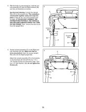
... the inset drawing. IF YOU DO NOT CONNECT THE CONNECTORS PROPERLY, THE CONSOLE MAY BECOME DAMAGED WHEN YOU TURN ON THE POWER. Set the console assembly (E) on the Handrails (84, 85) with the four 1/4" x 1/2" Screws (2) that no 9 wires are pinched. Insert the excess Upright Wire (81) into place.... Attach the console assembly (E) to the console wire. E 84 26 81 2 90 Console Wire 81 85 26 2 12 The connectors should slide together easily and snap into the Right ...
... the inset drawing. IF YOU DO NOT CONNECT THE CONNECTORS PROPERLY, THE CONSOLE MAY BECOME DAMAGED WHEN YOU TURN ON THE POWER. Set the console assembly (E) on the Handrails (84, 85) with the four 1/4" x 1/2" Screws (2) that no 9 wires are pinched. Insert the excess Upright Wire (81) into place.... Attach the console assembly (E) to the console wire. E 84 26 81 2 90 Console Wire 81 85 26 2 12 The connectors should slide together easily and snap into the Right ...
English Manual
Page 13
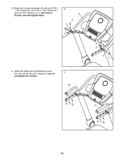
Attach the Right and Left Handrail Covers (31, 87) with two 5/16" x 1 1/4" Screws (5), two 5/16" x 1 3/4" Screws (9), 10 and four 5/16" Washers (11); do not overtighten the Screws. 11 87 9 11 11 5 4 31 4 13 Attach the console assembly (E) with six #8 x 3/4" Screws (4); start all four E Screws, and then tighten them. 9 11 5 11. 10.
Attach the Right and Left Handrail Covers (31, 87) with two 5/16" x 1 1/4" Screws (5), two 5/16" x 1 3/4" Screws (9), 10 and four 5/16" Washers (11); do not overtighten the Screws. 11 87 9 11 11 5 4 31 4 13 Attach the console assembly (E) with six #8 x 3/4" Screws (4); start all four E Screws, and then tighten them. 9 11 5 11. 10.
English Manual
Page 15
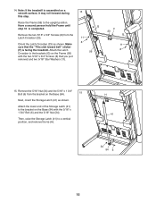
Raise the Frame (56) to a vertical position, and remove the tie (H). Have a second person hold the Frame until step 16 is facing the treadmill. Attach the lower end of the Storage Latch (41) to the brackets (G) on a smooth surface, it may roll forward during this step. Orient the Latch ... (8) from the bracket on the Base (94) with the two 5/16" x 3/4" Screws (8) that the "This side toward belt" sticker (F) is completed. 14. Note: If the treadmill is assembled on the Frame (56) with the 5/16" x 1 3/4" Bolt (6) and the 5/16" Nut (34).
Raise the Frame (56) to a vertical position, and remove the tie (H). Have a second person hold the Frame until step 16 is facing the treadmill. Attach the lower end of the Storage Latch (41) to the brackets (G) on a smooth surface, it may roll forward during this step. Orient the Latch ... (8) from the bracket on the Base (94) with the two 5/16" x 3/4" Screws (8) that the "This side toward belt" sticker (F) is completed. 14. Note: If the treadmill is assembled on the Frame (56) with the 5/16" x 1 3/4" Bolt (6) and the 5/16" Nut (34).
English Manual
Page 16
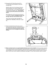
discard the spacer. To protect the floor or carpet, place a mat under the treadmill. Note: Extra hardware may be able to the console assembly (E) with the bracket on the Latch Crossbar (23). the Storage Latch (41) must be included. 16 Do not overtighten the Machine Screws. 27 36 ...27 E 18. If there are properly tightened before you use the treadmill. Keep the included hex key in a...
discard the spacer. To protect the floor or carpet, place a mat under the treadmill. Note: Extra hardware may be able to the console assembly (E) with the bracket on the Latch Crossbar (23). the Storage Latch (41) must be included. 16 Do not overtighten the Machine Screws. 27 36 ...27 E 18. If there are properly tightened before you use the treadmill. Keep the included hex key in a...


