
English Manual
Page 1
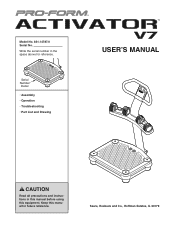
Sears, Roebuck and Co., Hoffman Estates, IL 60179 Keep this equipment. Model No. 831.14787.0 Serial No. Serial Number Decal • Assembly • Operation • Troubleshooting • Part List and Drawing USERʼS MANUAL CAUTION Read all precautions and instructions in the space above for future reference. Write the serial number in this manual before using this manual for reference.
Sears, Roebuck and Co., Hoffman Estates, IL 60179 Keep this equipment. Model No. 831.14787.0 Serial No. Serial Number Decal • Assembly • Operation • Troubleshooting • Part List and Drawing USERʼS MANUAL CAUTION Read all precautions and instructions in the space above for future reference. Write the serial number in this manual before using this manual for reference.
English Manual
Page 2
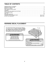
Apply the decal in the locations shown. Note: The decals may not be shown at actual size. 2 If a decal is missing or illegible, call 1-888-533-1333 and request a free replacement decal. TABLE OF CONTENTS WARNING DECAL PLACEMENT 2 IMPORTANT PRECAUTIONS 3 BEFORE YOU BEGIN 5 PART IDENTIFICATION CHART 6 ASSEMBLY 7 HOW TO USE THE VIBRATION PLATFORM 13 TROUBLESHOOTING 17 PART LIST 18 EXPLODED DRAWING 19 ORDERING REPLACEMENT PARTS Back Cover 90 DAY FULL WARRANTY Back Cover WARNING DECAL PLACEMENT The warning decals shown here have been applied in the location shown.
Apply the decal in the locations shown. Note: The decals may not be shown at actual size. 2 If a decal is missing or illegible, call 1-888-533-1333 and request a free replacement decal. TABLE OF CONTENTS WARNING DECAL PLACEMENT 2 IMPORTANT PRECAUTIONS 3 BEFORE YOU BEGIN 5 PART IDENTIFICATION CHART 6 ASSEMBLY 7 HOW TO USE THE VIBRATION PLATFORM 13 TROUBLESHOOTING 17 PART LIST 18 EXPLODED DRAWING 19 ORDERING REPLACEMENT PARTS Back Cover 90 DAY FULL WARRANTY Back Cover WARNING DECAL PLACEMENT The warning decals shown here have been applied in the location shown.
English Manual
Page 3
The vibration platform is intended only for home use only. Keep children under age 12 and pets away from the vibration platform; Keep your physician. Make sure that the dumbbells are secure in the weight rests when they are adequately informed of all precautions. 10. Before beginning any worn parts immediately. 6. Be careful when stepping down . 9. Do not place the vibration platform in a garage or covered patio, or near water. 5. Inspect and properly tighten all times. 7. Never allow more than one or more than 15 minutes per day and no responsibility for persons...
The vibration platform is intended only for home use only. Keep children under age 12 and pets away from the vibration platform; Keep your physician. Make sure that the dumbbells are secure in the weight rests when they are adequately informed of all precautions. 10. Before beginning any worn parts immediately. 6. Be careful when stepping down . 9. Do not place the vibration platform in a garage or covered patio, or near water. 5. Inspect and properly tighten all times. 7. Never allow more than one or more than 15 minutes per day and no responsibility for persons...
English Manual
Page 4
Use only a single-outlet surge suppressor that meets all of carrying 15 or more amps. Never leave the vibration platform unattended while it is not in this manual should be performed by an authorized service representative only. 4 Use the vibration platform and the included dumbbells only as the vibration platform. To purchase a surge suppressor, see your local Sears store or call the telephone number on the back cover of this manual and order part number 146148, or see page 14), plug the power cord into a surge suppressor (not included) and plug the surge suppressor into a ...
Use only a single-outlet surge suppressor that meets all of carrying 15 or more amps. Never leave the vibration platform unattended while it is not in this manual should be performed by an authorized service representative only. 4 Use the vibration platform and the included dumbbells only as the vibration platform. To purchase a surge suppressor, see your local Sears store or call the telephone number on the back cover of this manual and order part number 146148, or see page 14), plug the power cord into a surge suppressor (not included) and plug the surge suppressor into a ...
English Manual
Page 5
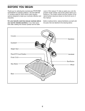
... whole body vibration options designed to make your benefit, read this manual carefully before contacting us. To help us assist you for selecting the revolutionary PROFORM® ACTIVATOR V7 vibration platform. BEFORE YOU BEGIN Thank you , note the product model number and serial number before you have questions after reading this manual, please...
... whole body vibration options designed to make your benefit, read this manual carefully before contacting us. To help us assist you for selecting the revolutionary PROFORM® ACTIVATOR V7 vibration platform. BEFORE YOU BEGIN Thank you , note the product model number and serial number before you have questions after reading this manual, please...
English Manual
Page 6
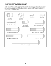
If a part is not in the hardware kit, check to identify small parts used in parentheses by each drawing is missing, call 1-888-533-1333. If a part is the key number of the part, from the PART LIST near the end of this manual. The number in assembly. Note: Some small parts may have been preattached. M10 Nylon Locknut (32) M10 Split Washer (38) M4 x 16mm Patch Screw (26) M4 x 19mm Screw (45) M5 x 38mm Screw (40) M10 x 20mm Patch Screw (28) M10 x 35mm Screw (34) M10 x 50mm Patch Screw (51) M10 x 55mm Patch Screw (20) M10 x 62mm Patch Screw (37) M10 x 68mm Bolt (55) M10 ...
If a part is not in the hardware kit, check to identify small parts used in parentheses by each drawing is missing, call 1-888-533-1333. If a part is the key number of the part, from the PART LIST near the end of this manual. The number in assembly. Note: Some small parts may have been preattached. M10 Nylon Locknut (32) M10 Split Washer (38) M4 x 16mm Patch Screw (26) M4 x 19mm Screw (45) M5 x 38mm Screw (40) M10 x 20mm Patch Screw (28) M10 x 35mm Screw (34) M10 x 50mm Patch Screw (51) M10 x 55mm Patch Screw (20) M10 x 62mm Patch Screw (37) M10 x 68mm Bolt (55) M10 ...
English Manual
Page 7
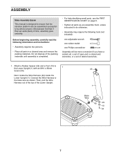
Attach a Rubber Spacer (29) and a Foot (13) to ensure that if they set of the packing materials until assembly is designed to 1 the Lower Upright (1) with an M10 x 35mm 43 Screw (34). Then, pull the Wire Harness out of the top of time, assembly goes smoothly. Connect the Wire Harness to the base wire as you assemble them, unless instructed to do otherwise. • Assembly may require the following information and instructions: • Assembly requires two persons. • Place all parts as shown. Do not dispose of ratchet wrenches. 1. Next, locate the Wire ...
Attach a Rubber Spacer (29) and a Foot (13) to ensure that if they set of the packing materials until assembly is designed to 1 the Lower Upright (1) with an M10 x 35mm 43 Screw (34). Then, pull the Wire Harness out of the top of time, assembly goes smoothly. Connect the Wire Harness to the base wire as you assemble them, unless instructed to do otherwise. • Assembly may require the following information and instructions: • Assembly requires two persons. • Place all parts as shown. Do not dispose of ratchet wrenches. 1. Next, locate the Wire ...
English Manual
Page 8
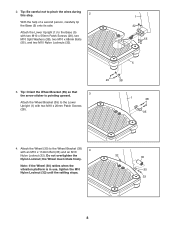
Tip: Be careful not to the Wheel Bracket (35) 4 with an M10 x 114mm Bolt (33) and an M10 Nylon Locknut (32). Do not overtighten the Nylon Locknut; 2. Tip: Orient the Wheel Bracket (35) so that the arrow sticker is in use, tighten the M10 Nylon Locknut (32) until the rattling stops. 32 30 35 33 8 Note: If the Wheel (30) rattles when the vibration platform is pointing upward. 3 Attach the Wheel Bracket (35) to the Base (5) with two M10 x 20mm Patch Screws (28). 20 38 1 28 35 4. the Wheel must rotate freely. Attach the Lower Upright (1) to the Lower Upright (1) ...
Tip: Be careful not to the Wheel Bracket (35) 4 with an M10 x 114mm Bolt (33) and an M10 Nylon Locknut (32). Do not overtighten the Nylon Locknut; 2. Tip: Orient the Wheel Bracket (35) so that the arrow sticker is in use, tighten the M10 Nylon Locknut (32) until the rattling stops. 32 30 35 33 8 Note: If the Wheel (30) rattles when the vibration platform is pointing upward. 3 Attach the Wheel Bracket (35) to the Base (5) with two M10 x 20mm Patch Screws (28). 20 38 1 28 35 4. the Wheel must rotate freely. Attach the Lower Upright (1) to the Lower Upright (1) ...
English Manual
Page 9
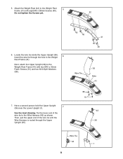
Locate the wire tie inside the Upper Upright (36). Next, attach the Upper Upright (36) to the Weight Rest Frame (41) with eight M5 x 38mm Screws (40). 5 Do not tighten the Screws yet. 42 6. Insert the wire tie through the Upper Upright (36). 40 40 41 40 40 Wire Tie 36 Hole 41 38 51 43 36 Wire Tie 43 1 9 Tie the lower end of the wire tie until the Wire Harness is routed through the hole in the Weight 6 Rest Frame (41). Attach the Weight Rest (42) to the Wire Harness (43) as shown. Have a second person hold the Upper Upright (36) near the Lower Upright (1). 7 See the ...
Locate the wire tie inside the Upper Upright (36). Next, attach the Upper Upright (36) to the Weight Rest Frame (41) with eight M5 x 38mm Screws (40). 5 Do not tighten the Screws yet. 42 6. Insert the wire tie through the Upper Upright (36). 40 40 41 40 40 Wire Tie 36 Hole 41 38 51 43 36 Wire Tie 43 1 9 Tie the lower end of the wire tie until the Wire Harness is routed through the hole in the Weight 6 Rest Frame (41). Attach the Weight Rest (42) to the Wire Harness (43) as shown. Have a second person hold the Upper Upright (36) near the Lower Upright (1). 7 See the ...
English Manual
Page 10
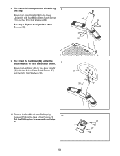
Tighten the eight M5 x 38mm Screws (40). 36 38 28 28 38 1 9. Tip: Be careful not to the Upper Upright (36) with four M10 x 20mm Patch Screws (28) and four M10 Split Washers (38). See step 5. Set the Self-tapping Screws aside until step 13. 3 27 27 10 8. Attach the Upper Upright (36) to the Lower Upright (1) with two M10 x 62mm Patch Screws (37) and two M10 Split Washers (38). 37 39 38 36 "R" 10. Remove the four M4 x 12mm Self-tapping 10 Screws (27) from the back of the Console (3). Tip: Orient the Handlebar (39) so that the sticker with an "R" is in the ...
Tighten the eight M5 x 38mm Screws (40). 36 38 28 28 38 1 9. Tip: Be careful not to the Upper Upright (36) with four M10 x 20mm Patch Screws (28) and four M10 Split Washers (38). See step 5. Set the Self-tapping Screws aside until step 13. 3 27 27 10 8. Attach the Upper Upright (36) to the Lower Upright (1) with two M10 x 62mm Patch Screws (37) and two M10 Split Washers (38). 37 39 38 36 "R" 10. Remove the four M4 x 12mm Self-tapping 10 Screws (27) from the back of the Console (3). Tip: Orient the Handlebar (39) so that the sticker with an "R" is in the ...
English Manual
Page 11
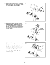
Do not tighten the Screws yet. 36 3 26 12. 11. Tip: Be careful not to pinch the wires during this step. 13 Attach the front of the Console (3) to the Ground Wire (52). While a second person holds the Front of the Console (3) near the Upper Upright (36), con- 12 nect the console ground wire to the back of the Console (3) to the Wire Harness (43). Then, insert the wires into the Upper Upright. 3 Console Wire 43 36 Console Ground Wire 52 13. tapping Screws (27) you removed in step 10 3 and an M4 x 19mm Screw (45). See step 11. Tighten the two M4 x 16mm ...
Do not tighten the Screws yet. 36 3 26 12. 11. Tip: Be careful not to pinch the wires during this step. 13 Attach the front of the Console (3) to the Ground Wire (52). While a second person holds the Front of the Console (3) near the Upper Upright (36), con- 12 nect the console ground wire to the back of the Console (3) to the Wire Harness (43). Then, insert the wires into the Upper Upright. 3 Console Wire 43 36 Console Ground Wire 52 13. tapping Screws (27) you removed in step 10 3 and an M4 x 19mm Screw (45). See step 11. Tighten the two M4 x 16mm ...
English Manual
Page 12
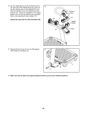
Then, lift the two selector pins and slide them to the adjustment holes marked "2.5." Make sure that all parts are properly tightened before you use the vibration platform. 12 Set ten weight plates into the Receptacle 15 (18) located on a Dumbbell (44), and slide the selector pins to the adjustment holes marked "15." Plug the Power Cord (17) into the indicated slots in the right side of the Weight Rest (42). 14. Next, lift 14 the two selector pins on the Base (5). 5 18 17 16. Repeat this step with the other Dumbbell (44). 44 42 Selector Pins 44 Weight Plates Slots...
Then, lift the two selector pins and slide them to the adjustment holes marked "2.5." Make sure that all parts are properly tightened before you use the vibration platform. 12 Set ten weight plates into the Receptacle 15 (18) located on a Dumbbell (44), and slide the selector pins to the adjustment holes marked "15." Plug the Power Cord (17) into the indicated slots in the right side of the Weight Rest (42). 14. Next, lift 14 the two selector pins on the Base (5). 5 18 17 16. Repeat this step with the other Dumbbell (44). 44 42 Selector Pins 44 Weight Plates Slots...
English Manual
Page 13
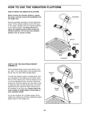
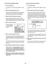
Carefully move the vibration platform over an uneven surface. Do not move the vibration platform to both sides of weight plates, first set a dumbbell on the weight rest. Always attach the same number of weight plates to the desired location. Hold the handlebar and place one of the selector pins, slide the selector pin to make sure that the unattached weight plates remain on the weight rest as shown. Handlebar Wheel Dumbbell HOW TO USE THE ADJUSTABLE-WEIGHT DUMBBELLS Each dumbbell handle can also be used without weight plates. Next, lift one of the adjustment holes, ...
Carefully move the vibration platform over an uneven surface. Do not move the vibration platform to both sides of weight plates, first set a dumbbell on the weight rest. Always attach the same number of weight plates to the desired location. Hold the handlebar and place one of the selector pins, slide the selector pin to make sure that the unattached weight plates remain on the weight rest as shown. Handlebar Wheel Dumbbell HOW TO USE THE ADJUSTABLE-WEIGHT DUMBBELLS Each dumbbell handle can also be used without weight plates. Next, lift one of the adjustment holes, ...
English Manual
Page 14
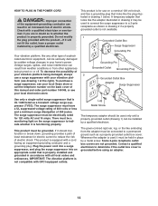
Check with the product-if it will not fit the outlet, have a UL suppressed voltage rating of 400 volts or less and a minimum surge dissipation of 450 joules. The surge suppressor must be grounded. This product must be electrically rated for 120 volts AC and 15 amps. Contact a qualified electrician to whether the product is grounded before using an adapter. 14 Do not modify the plug provided with a qualified electrician or serviceman if you are not grounded. To purchase a surge suppressor, see drawing 1 at the right). If it is properly installed and grounded in place by...
Check with the product-if it will not fit the outlet, have a UL suppressed voltage rating of 400 volts or less and a minimum surge dissipation of 450 joules. The surge suppressor must be grounded. This product must be electrically rated for 120 volts AC and 15 amps. Contact a qualified electrician to whether the product is grounded before using an adapter. 14 Do not modify the plug provided with a qualified electrician or serviceman if you are not grounded. To purchase a surge suppressor, see drawing 1 at the right). If it is properly installed and grounded in place by...
English Manual
Page 15
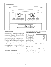
IFIT programs control the time and frequency of the vibration platform while the voice of a personal trainer coaches you and motivates you do not do this, the console or other electronic components may become damaged. IFIT cards are also available at select stores. If you through your workouts more effective and enjoyable. Plug the power cord into a 120-volt outlet. form near the power cord. iFIT cards are available separately. Next, locate the reset/off circuit breaker on the base of your feet. 15 CONSOLE DIAGRAM CONSOLE FEATURES The console offers a selection of features ...
IFIT programs control the time and frequency of the vibration platform while the voice of a personal trainer coaches you and motivates you do not do this, the console or other electronic components may become damaged. IFIT cards are also available at select stores. If you through your workouts more effective and enjoyable. Plug the power cord into a 120-volt outlet. form near the power cord. iFIT cards are available separately. Next, locate the reset/off circuit breaker on the base of your feet. 15 CONSOLE DIAGRAM CONSOLE FEATURES The console offers a selection of features ...
English Manual
Page 16
The display will begin guiding you are finished, switch the reset/off circuit breaker to stop . Turn on the power. make sure that you are facing the slot. Press the stop button (see the drawing above) on the platform to the off position and unplug the power cord. 16 A moment after you select a program, the voice of a personal trainer will show which frequency you have selected. 4. When you through your workout. 3. Turn on the power. Press the desired frequency button to select a vibration time of 25, 30, or 35 hertz. Start a vibration session. Stop Button ...
The display will begin guiding you are finished, switch the reset/off circuit breaker to stop . Turn on the power. make sure that you are facing the slot. Press the stop button (see the drawing above) on the platform to the off position and unplug the power cord. 16 A moment after you select a program, the voice of a personal trainer will show which frequency you have selected. 4. When you through your workout. 3. Turn on the power. Press the desired frequency button to select a vibration time of 25, 30, or 35 hertz. Start a vibration session. Stop Button ...
English Manual
Page 17
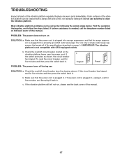
Most vibration platform problems can be solved by following the simple steps below. If further assistance is plugged into a surge suppressor, and that meets all parts of the vibration platform regularly. Make sure that the power cord is needed, call the telephone number listed on the back cover of this manual. 17 To reset the circuit breaker, wait for five minutes and then press the switch back in . Replace any worn parts immediately. Use only a single-outlet surge suppressor that the surge suppressor is plugged in . b. Check the reset/off circuit breaker (see the back cover ...
Most vibration platform problems can be solved by following the simple steps below. If further assistance is plugged into a surge suppressor, and that meets all parts of the vibration platform regularly. Make sure that the power cord is needed, call the telephone number listed on the back cover of this manual. 17 To reset the circuit breaker, wait for five minutes and then press the switch back in . Replace any worn parts immediately. Use only a single-outlet surge suppressor that the surge suppressor is plugged in . b. Check the reset/off circuit breaker (see the back cover ...
English Manual
Page 18
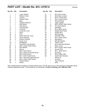
Qty. Hex Key * - Description Key No. Qty. Description 1 1 Lower Upright 2 1 Platform Cover 3 1 Console 4 1 Platform Plate 5 1 Base 6 1 Vibration Platform 7 1 Stop Button 8 1 Start Button 9 1 Controller Box 10 1 Controller 11 1 Controller Cover 12 1 Motor 13 5 Foot 14 4 Shock Absorber Cover 15 4 Shock Absorber 16 4 Platform Endcap 17 1 Power Cord 18 1 Receptacle 19 1 Reset/Off Circuit Breaker 20 2 M10 x 55mm Patch Screw 21 2 Star Washer 22 2 Spring 23 2 M8 x 16mm Screw 24 4 M10 x 46mm Flat Head Screw 25 4...
Qty. Hex Key * - Description Key No. Qty. Description 1 1 Lower Upright 2 1 Platform Cover 3 1 Console 4 1 Platform Plate 5 1 Base 6 1 Vibration Platform 7 1 Stop Button 8 1 Start Button 9 1 Controller Box 10 1 Controller 11 1 Controller Cover 12 1 Motor 13 5 Foot 14 4 Shock Absorber Cover 15 4 Shock Absorber 16 4 Platform Endcap 17 1 Power Cord 18 1 Receptacle 19 1 Reset/Off Circuit Breaker 20 2 M10 x 55mm Patch Screw 21 2 Star Washer 22 2 Spring 23 2 M8 x 16mm Screw 24 4 M10 x 46mm Flat Head Screw 25 4...
English Manual
Page 19
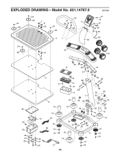
EXPLODED DRAWING-Model No. 831.14787.0 R0709A 24 39 27 48 7 24 8 37 38 37 3 27 48 22 24 38 45 48 26 52 2 53 36 24 48 49 54 50 46 47 25 42 21 44 23 40 40 11 38 41 51 40 4 31 38 40 28 31 10 31 28 9 38 32 30 1 6 15 14 12 43 16 56 13 34 46 47 25 17 15 14 16 13 15 14 53 32 18 19 55 35 29 13 34 33 28 15 14 34 20 38 16 5 13 16 34 13 34 19
EXPLODED DRAWING-Model No. 831.14787.0 R0709A 24 39 27 48 7 24 8 37 38 37 3 27 48 22 24 38 45 48 26 52 2 53 36 24 48 49 54 50 46 47 25 42 21 44 23 40 40 11 38 41 51 40 4 31 38 40 28 31 10 31 28 9 38 32 30 1 6 15 14 12 43 16 56 13 34 46 47 25 17 15 14 16 13 15 14 53 32 18 19 55 35 29 13 34 33 28 15 14 34 20 38 16 5 13 16 34 13 34 19

English Manual
Page 20
There is used commercially or for free repair (or replacement if repair proves impossible). only) www.sears.com To purchase a protection agreement (U.S.A.) or maintenance agreement (Canada) on a product serviced by Sears: 1-800-827-6655 (U.S.A.) 1-800-361-6665 (Canada) Para pedir servicio de reparación a domicilio, y para ordenar piezas: 1-888-SU-HOGAR® (1-888-784-6427) ® Registered Trademark / TM Trademark / SM Service Mark of Sears Brands, LLC ® Marca Registrada / TM Marca de Fábrica / SM Marca de Servicio de Sears Brands, LLC 90 DAY FULL WARRANTY If this...
There is used commercially or for free repair (or replacement if repair proves impossible). only) www.sears.com To purchase a protection agreement (U.S.A.) or maintenance agreement (Canada) on a product serviced by Sears: 1-800-827-6655 (U.S.A.) 1-800-361-6665 (Canada) Para pedir servicio de reparación a domicilio, y para ordenar piezas: 1-888-SU-HOGAR® (1-888-784-6427) ® Registered Trademark / TM Trademark / SM Service Mark of Sears Brands, LLC ® Marca Registrada / TM Marca de Fábrica / SM Marca de Servicio de Sears Brands, LLC 90 DAY FULL WARRANTY If this...
