
English Manual
Page 1
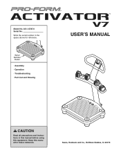
Sears, Roebuck and Co., Hoffman Estates, IL 60179 Serial Number Decal • Assembly • Operation • Troubleshooting • Part List and Drawing USERʼS MANUAL CAUTION Read all precautions and instructions in the space above for future reference. Model No. 831.14787.0 Serial No. Keep this equipment. Write the serial number in this manual before using this manual for reference.
Sears, Roebuck and Co., Hoffman Estates, IL 60179 Serial Number Decal • Assembly • Operation • Troubleshooting • Part List and Drawing USERʼS MANUAL CAUTION Read all precautions and instructions in the space above for future reference. Model No. 831.14787.0 Serial No. Keep this equipment. Write the serial number in this manual before using this manual for reference.
English Manual
Page 2
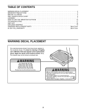
Note: The decals may not be shown at actual size. 2 If a decal is missing or illegible, call 1-888-533-1333 and request a free replacement decal. Apply the decal in the locations shown. TABLE OF CONTENTS WARNING DECAL PLACEMENT 2 IMPORTANT PRECAUTIONS 3 BEFORE YOU BEGIN 5 PART IDENTIFICATION CHART 6 ASSEMBLY 7 HOW TO USE THE VIBRATION PLATFORM 13 TROUBLESHOOTING 17 PART LIST 18 EXPLODED DRAWING 19 ORDERING REPLACEMENT PARTS Back Cover 90 DAY FULL WARRANTY Back Cover WARNING DECAL PLACEMENT The warning decals shown here have been applied in the location shown.
Note: The decals may not be shown at actual size. 2 If a decal is missing or illegible, call 1-888-533-1333 and request a free replacement decal. Apply the decal in the locations shown. TABLE OF CONTENTS WARNING DECAL PLACEMENT 2 IMPORTANT PRECAUTIONS 3 BEFORE YOU BEGIN 5 PART IDENTIFICATION CHART 6 ASSEMBLY 7 HOW TO USE THE VIBRATION PLATFORM 13 TROUBLESHOOTING 17 PART LIST 18 EXPLODED DRAWING 19 ORDERING REPLACEMENT PARTS Back Cover 90 DAY FULL WARRANTY Back Cover WARNING DECAL PLACEMENT The warning decals shown here have been applied in the location shown.
English Manual
Page 3
... the responsibility of the owner to you exercise on a level surface, with pre-existing health problems. 2. your physician before moving the vibration platform. 3 Place the vibration platform on the vibration platform. 3. Replace any exercise program, consult your back. Always remove the dumbbells from the vibration platform; Be careful when stepping down . 9. Do not use only. Inspect and properly tighten all precautions. 10...
... the responsibility of the owner to you exercise on a level surface, with pre-existing health problems. 2. your physician before moving the vibration platform. 3 Place the vibration platform on the vibration platform. 3. Replace any exercise program, consult your back. Always remove the dumbbells from the vibration platform; Be careful when stepping down . 9. Do not use only. Inspect and properly tighten all precautions. 10...
English Manual
Page 4
... store. 19. form. Use the vibration platform and the included dumbbells only as the vibration platform. No other than the procedures in this manual and order part number 146148, or see your local Sears store or call the telephone number on page 14. Keep the power cord away from heated surfaces. 20. Always unplug the power cord and switch the reset/off circuit...
... store. 19. form. Use the vibration platform and the included dumbbells only as the vibration platform. No other than the procedures in this manual and order part number 146148, or see your local Sears store or call the telephone number on page 14. Keep the power cord away from heated surfaces. 20. Always unplug the power cord and switch the reset/off circuit...
English Manual
Page 5
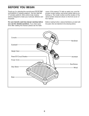
... this manual. Console Dumbbell Weight Rest Reset/Off Circuit Breaker Power Cord Stop Button Base Handlebar Dumbbell Start Button Wheel 5 Before reading further, please familiarize yourself with the parts that are shown on the front cover of this manual carefully before contacting us. To help us assist you, note the product model number and serial number before you for selecting the revolutionary PROFORM® ACTIVATOR V7 vibration platform. For your workouts...
... this manual. Console Dumbbell Weight Rest Reset/Off Circuit Breaker Power Cord Stop Button Base Handlebar Dumbbell Start Button Wheel 5 Before reading further, please familiarize yourself with the parts that are shown on the front cover of this manual carefully before contacting us. To help us assist you, note the product model number and serial number before you for selecting the revolutionary PROFORM® ACTIVATOR V7 vibration platform. For your workouts...
English Manual
Page 6
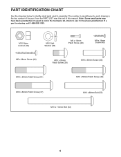
... Screw (34) M10 x 50mm Patch Screw (51) M10 x 55mm Patch Screw (20) M10 x 62mm Patch Screw (37) M10 x 68mm Bolt (55) M10 x 114mm Bolt (33) 6 PART IDENTIFICATION CHART See the drawings below to see if it has been preattached. Note: Some small parts may have been preattached. If a part is the key number of the part, from the PART LIST near the end of this manual...
... Screw (34) M10 x 50mm Patch Screw (51) M10 x 55mm Patch Screw (20) M10 x 62mm Patch Screw (37) M10 x 68mm Bolt (55) M10 x 114mm Bolt (33) 6 PART IDENTIFICATION CHART See the drawings below to see if it has been preattached. Note: Some small parts may have been preattached. If a part is the key number of the part, from the PART LIST near the end of this manual...
English Manual
Page 7
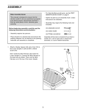
.... • Assembly may require the following information and instructions: • Assembly requires two persons. • Place all parts as shown. Connect the Wire Harness to the base wire as you assemble them, unless instructed to 1 the Lower Upright (1) with an M10 x 35mm 43 Screw (34). Most people find that the vibration platform can be more convenient if you have a socket set, a set of open-end or...
.... • Assembly may require the following information and instructions: • Assembly requires two persons. • Place all parts as shown. Connect the Wire Harness to the base wire as you assemble them, unless instructed to 1 the Lower Upright (1) with an M10 x 35mm 43 Screw (34). Most people find that the vibration platform can be more convenient if you have a socket set, a set of open-end or...
English Manual
Page 8
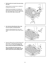
...) to pinch the wires during this step. 2 With the help of a second person, carefully tip the Base (5) onto its side. 2. Attach the Lower Upright (1) to the Wheel Bracket (35) 4 with two M10 x 20mm Patch Screws (28). 20 38 1 28 35 4. Tip: Orient the Wheel Bracket (35) so that the arrow sticker is in use, tighten the M10 Nylon...
...) to pinch the wires during this step. 2 With the help of a second person, carefully tip the Base (5) onto its side. 2. Attach the Lower Upright (1) to the Wheel Bracket (35) 4 with two M10 x 20mm Patch Screws (28). 20 38 1 28 35 4. Tip: Orient the Wheel Bracket (35) so that the arrow sticker is in use, tighten the M10 Nylon...
English Manual
Page 9
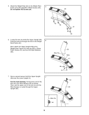
Locate the wire tie inside the Upper Upright (36). Tie the lower end of the wire tie until the Wire Harness is routed through the hole in the Weight 6 Rest Frame (41). Attach the Weight Rest (42) to the Weight Rest Frame (41) with eight M5 x 38mm Screws (40). 5 Do not tighten the Screws yet. 42 6. Next, attach the Upper Upright (36) to the Weight Rest Frame (41...
Locate the wire tie inside the Upper Upright (36). Tie the lower end of the wire tie until the Wire Harness is routed through the hole in the Weight 6 Rest Frame (41). Attach the Weight Rest (42) to the Weight Rest Frame (41) with eight M5 x 38mm Screws (40). 5 Do not tighten the Screws yet. 42 6. Next, attach the Upper Upright (36) to the Weight Rest Frame (41...
English Manual
Page 10
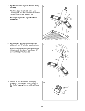
... an "R" is in the location shown. 9 Attach the Handlebar (39) to pinch the wires during 8 this step. Remove the four M4 x 12mm Self-tapping 10 Screws (27) from the back of the Console (3). Tip: Be careful not to the Upper Upright (36) with four M10 x 20mm Patch Screws (28) and four M10 Split Washers (38). Tighten the eight M5 x 38mm...
... an "R" is in the location shown. 9 Attach the Handlebar (39) to pinch the wires during 8 this step. Remove the four M4 x 12mm Self-tapping 10 Screws (27) from the back of the Console (3). Tip: Be careful not to the Upper Upright (36) with four M10 x 20mm Patch Screws (28) and four M10 Split Washers (38). Tighten the eight M5 x 38mm...
English Manual
Page 11
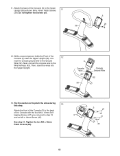
Next, connect the console wire to the Ground Wire (52). Then, insert the wires into the Upper Upright. 3 Console Wire 43 36 Console Ground Wire 52 13. See step 11. 11. Attach the back of the Console (3) to the Upper Upright (36) with the four M4 x 12mm Self- tapping Screws (27) you removed in step 10 3 and an M4 x 19mm Screw (45). Tighten the two M4 x 16mm Patch Screws (26). 3 27...
Next, connect the console wire to the Ground Wire (52). Then, insert the wires into the Upper Upright. 3 Console Wire 43 36 Console Ground Wire 52 13. See step 11. 11. Attach the back of the Console (3) to the Upper Upright (36) with the four M4 x 12mm Self- tapping Screws (27) you removed in step 10 3 and an M4 x 19mm Screw (45). Tighten the two M4 x 16mm Patch Screws (26). 3 27...
English Manual
Page 12
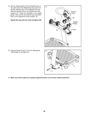
Set ten weight plates into the Receptacle 15 (18) located on the Base (5). 5 18 17 16. Next, lift 14 the two selector pins on the weight plates. Place the Dumbbell on a Dumbbell (44), and slide the selector pins to the adjustment holes marked "15." Make sure that all parts are properly tightened before you use the vibration platform. 12 Plug the Power Cord (17...
Set ten weight plates into the Receptacle 15 (18) located on the Base (5). 5 18 17 16. Next, lift 14 the two selector pins on the weight plates. Place the Dumbbell on a Dumbbell (44), and slide the selector pins to the adjustment holes marked "15." Make sure that all parts are properly tightened before you use the vibration platform. 12 Plug the Power Cord (17...
English Manual
Page 13
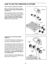
... adjustment holes, and then release the selector pin. Always attach the same number of weight plates to make sure that the unattached weight plates remain on the wheel. Hold the handlebar and place one of the selector pins, slide the selector pin to the desired location. Rock the selector pin from the weight rest. Dumbbell Selector Pin Weight Rest Handle Weight Plates 13 Carefully move...
... adjustment holes, and then release the selector pin. Always attach the same number of weight plates to make sure that the unattached weight plates remain on the wheel. Hold the handlebar and place one of the selector pins, slide the selector pin to the desired location. Rock the selector pin from the weight rest. Dumbbell Selector Pin Weight Rest Handle Weight Plates 13 Carefully move...
English Manual
Page 14
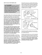
...-if it should be used only until a properly grounded outlet (drawing 1) can result from weather conditions or from the adapter must be grounded. To decrease the possibility of your homeʼs power. The surge suppressor must be a monitoring light on the back cover of this manual and order part number 146148, or see your local Sears store or call the...
...-if it should be used only until a properly grounded outlet (drawing 1) can result from weather conditions or from the adapter must be grounded. To decrease the possibility of your homeʼs power. The surge suppressor must be a monitoring light on the back cover of this manual and order part number 146148, or see your local Sears store or call the...
English Manual
Page 15
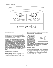
... console also features the new iFIT Interactive Workout System. Plug the power cord into a 120-volt outlet. form near the power cord. The iFIT Interactive Workout System is in the reset position. Then, plug the power cord into the receptacle on the base of the vibration platform (see assembly step 15 on the balls of your feet. 15 CONSOLE DIAGRAM CONSOLE FEATURES The console offers a selection of features designed to www.iFIT...
... console also features the new iFIT Interactive Workout System. Plug the power cord into a 120-volt outlet. form near the power cord. The iFIT Interactive Workout System is in the reset position. Then, plug the power cord into the receptacle on the base of the vibration platform (see assembly step 15 on the balls of your feet. 15 CONSOLE DIAGRAM CONSOLE FEATURES The console offers a selection of features designed to www.iFIT...
English Manual
Page 16
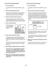
... display will show which length of a personal trainer will automatically stop button (see the drawing above) on the power. Press the start button on the platform to start button to alert you, and the vibration platform will begin guiding you select a program, the voice of time you use an iFIT program, insert an iFIT card into the iFIT slot; Insert an iFIT card and select a program. HOW TO USE THE MANUAL MODE 1. Press the stop . Press the start...
... display will show which length of a personal trainer will automatically stop button (see the drawing above) on the power. Press the start button on the platform to start button to alert you, and the vibration platform will begin guiding you select a program, the voice of time you use an iFIT program, insert an iFIT card into the iFIT slot; Insert an iFIT card and select a program. HOW TO USE THE MANUAL MODE 1. Press the stop . Press the start...
English Manual
Page 17
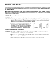
... steps listed. do not use SOLUTION: a. Find the symptom that meets all parts of the vibration platform can be cleaned with GFCI-equipped outlets. b. If the power cord is not compatible with a damp cloth and a mild, non-abrasive detergent; TROUBLESHOOTING Inspect all of this manual. Check the reset/off circuit breaker located on page 14. Replace any worn parts immediately. c Tripped Reset PROBLEM: The power turns...
... steps listed. do not use SOLUTION: a. Find the symptom that meets all parts of the vibration platform can be cleaned with GFCI-equipped outlets. b. If the power cord is not compatible with a damp cloth and a mild, non-abrasive detergent; TROUBLESHOOTING Inspect all of this manual. Check the reset/off circuit breaker located on page 14. Replace any worn parts immediately. c Tripped Reset PROBLEM: The power turns...
English Manual
Page 18
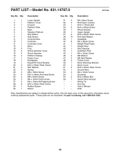
... illustrated. Qty. Description Key No. Qty. Wiring Tie * - Userʼs Manual * - PART LIST-Model No. 831.14787.0 R0709A Key No. Description 1 1 Lower Upright 2 1 Platform Cover 3 1 Console 4 1 Platform Plate 5 1 Base 6 1 Vibration Platform 7 1 Stop Button 8 1 Start Button 9 1 Controller Box 10 1 Controller 11 1 Controller Cover 12 1 Motor 13 5 Foot 14 4 Shock Absorber Cover 15 4 Shock Absorber 16 4 Platform Endcap 17 1 Power Cord 18 1 Receptacle 19 1 Reset/Off Circuit Breaker 20 2 M10 x 55mm Patch Screw 21 2 Star Washer...
... illustrated. Qty. Description Key No. Qty. Wiring Tie * - Userʼs Manual * - PART LIST-Model No. 831.14787.0 R0709A Key No. Description 1 1 Lower Upright 2 1 Platform Cover 3 1 Console 4 1 Platform Plate 5 1 Base 6 1 Vibration Platform 7 1 Stop Button 8 1 Start Button 9 1 Controller Box 10 1 Controller 11 1 Controller Cover 12 1 Motor 13 5 Foot 14 4 Shock Absorber Cover 15 4 Shock Absorber 16 4 Platform Endcap 17 1 Power Cord 18 1 Receptacle 19 1 Reset/Off Circuit Breaker 20 2 M10 x 55mm Patch Screw 21 2 Star Washer...
English Manual
Page 19
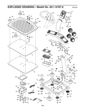
EXPLODED DRAWING-Model No. 831.14787.0 R0709A 24 39 27 48 7 24 8 37 38 37 3 27 48 22 24 38 45 48 26 52 2 53 36 24 48 49 54 50 46 47 25 42 21 44 23 40 40 11 38 41 51 40 4 31 38 40 28 31 10 31 28 9 38 32 30 1 6 15 14 12 43 16 56 13 34 46 47 25 17 15 14 16 13 15 14 53 32 18 19 55 35 29 13 34 33 28 15 14 34 20 38 16 5 13 16 34 13 34 19
EXPLODED DRAWING-Model No. 831.14787.0 R0709A 24 39 27 48 7 24 8 37 38 37 3 27 48 22 24 38 45 48 26 52 2 53 36 24 48 49 54 50 46 47 25 42 21 44 23 40 40 11 38 41 51 40 4 31 38 40 28 31 10 31 28 9 38 32 30 1 6 15 14 12 43 16 56 13 34 46 47 25 17 15 14 16 13 15 14 53 32 18 19 55 35 29 13 34 33 28 15 14 34 20 38 16 5 13 16 34 13 34 19
English Manual
Page 20
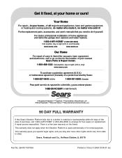
... fixed, at your home-of all major brand appliances, lawn and garden equipment, or heating and cooling systems, no matter who made it, no matter who sold it -yourself. There is used commercially or for free repair (or replacement if repair proves impossible). This warranty does not apply when the Vibration Platform is a five year warranty on a product serviced by Sears...
... fixed, at your home-of all major brand appliances, lawn and garden equipment, or heating and cooling systems, no matter who made it, no matter who sold it -yourself. There is used commercially or for free repair (or replacement if repair proves impossible). This warranty does not apply when the Vibration Platform is a five year warranty on a product serviced by Sears...


