

Owners Manual
Page 1
....-Fri., 6 a.m.-6 p.m. 8 MPHMOTIVATIONAL FITNESS TRAK TM ....... .... ... 1.25 HORSEPOWER DC MOTOR • CALORIE/PULSE MONITOR • AUTO INCLINE PRO•FORM® Model No. If you have questions, or find there are committed to you complete satisfaction through direct assistance from our factory. MST CAUTION: Read all safety precautions and instructions in this manual carefully before using this manual for future reference. 0 OWNER'S MANUAL The trained technicians on...
....-Fri., 6 a.m.-6 p.m. 8 MPHMOTIVATIONAL FITNESS TRAK TM ....... .... ... 1.25 HORSEPOWER DC MOTOR • CALORIE/PULSE MONITOR • AUTO INCLINE PRO•FORM® Model No. If you have questions, or find there are committed to you complete satisfaction through direct assistance from our factory. MST CAUTION: Read all safety precautions and instructions in this manual carefully before using this manual for future reference. 0 OWNER'S MANUAL The trained technicians on...

Owners Manual
Page 2
... power cord or plug is damaged, or if the treadmill is not in use the treadmill with a three-wire conductor. 3. Always unplug the power cord before using the treadmill. Adjust the speed slowly to persons, read the following important safety precautions and information before operating the treadmill. 1. Never move the walking belt while the power is turned off when the treadmill is not working properly.) 4. Use the treadmill only as an exercise aid in determining heart rate...
... power cord or plug is damaged, or if the treadmill is not in use the treadmill with a three-wire conductor. 3. Always unplug the power cord before using the treadmill. Adjust the speed slowly to persons, read the following important safety precautions and information before operating the treadmill. 1. Never move the walking belt while the power is turned off when the treadmill is not working properly.) 4. Use the treadmill only as an exercise aid in determining heart rate...

Owners Manual
Page 3
... -the-art technology with the parts labeled. Console Speed Control Knob Power Indicator Incline Indicator Electronic Monitor Handrail Side Rail Incline Control Lever Safety Key/Clip Foot Rail Roller Guard Back Rear Roller Adjustment Bolt Motor Hood Walking Belt Lock Knob Front Circuit Breaker Right Side Walking Platform Power Cord 3 TABLE OF CONTENTS Before You Begin Assembly Operation and Adjustment Trouble-Shooting and Storage Conditioning Guidelines Part List Exploded Drawing Ordering Replacement Parts Warranty 3 4 5 6 9 10 11 Back Cover Back Cover BEFORE YOU BEGIN Thank you...
... -the-art technology with the parts labeled. Console Speed Control Knob Power Indicator Incline Indicator Electronic Monitor Handrail Side Rail Incline Control Lever Safety Key/Clip Foot Rail Roller Guard Back Rear Roller Adjustment Bolt Motor Hood Walking Belt Lock Knob Front Circuit Breaker Right Side Walking Platform Power Cord 3 TABLE OF CONTENTS Before You Begin Assembly Operation and Adjustment Trouble-Shooting and Storage Conditioning Guidelines Part List Exploded Drawing Ordering Replacement Parts Warranty 3 4 5 6 9 10 11 Back Cover Back Cover BEFORE YOU BEGIN Thank you...

Owners Manual
Page 4
...parts are tightened securely before using the treadmill. 78 76 79 1 40 o 79 40 11 ;,ifg-' 14 4 Reach under the Console, and tighten the Bolt into the Console far enough to a vertical position. Make sure that all parts are included before beginning. 1. ASSEMBLY Set the treadmill in the Upright Post for the following steps... onto the end of the Side Rail (79) with the Lock Knob Washer (24), into the opening in the Frame (40). Tighten the Lock Knob (see step 1). Raise the Upright Post (13) to attach the Bolt, roll back the Side Rail Foam Grip (78) slightly. 3. ...
...parts are tightened securely before using the treadmill. 78 76 79 1 40 o 79 40 11 ;,ifg-' 14 4 Reach under the Console, and tighten the Bolt into the Console far enough to a vertical position. Make sure that all parts are included before beginning. 1. ASSEMBLY Set the treadmill in the Upright Post for the following steps... onto the end of the Side Rail (79) with the Lock Knob Washer (24), into the opening in the Frame (40). Tighten the Lock Knob (see step 1). Raise the Upright Post (13) to attach the Bolt, roll back the Side Rail Foam Grip (78) slightly. 3. ...

Owners Manual
Page 5
... POWER CORD, lift each side of the walking belt and prevent exces- OPERATION AND ADJUSTMENT GROUNDING INSTRUCTIONS This product must be applied after every 10 hours of use of electric shock. If it must be applied to reduce the risk of the treadmill. DANGER: Improper connection of electric shock. The temporary adapter should also be grounded. Do not modify the plug...
... POWER CORD, lift each side of the walking belt and prevent exces- OPERATION AND ADJUSTMENT GROUNDING INSTRUCTIONS This product must be applied after every 10 hours of use of electric shock. If it must be applied to reduce the risk of the treadmill. DANGER: Improper connection of electric shock. The temporary adapter should also be grounded. Do not modify the plug...

Owners Manual
Page 6
... clothing. Turning the knob counterclockwise decreases the speed. 6. INCLINE ADJUSTMENT To vary the intensity of the console. To decrease the incline, stand toward the back of the treadmill. TROUBLE-SHOOTING AND STORAGE Most treadmill problems can be pulled from the console, instantly turning the power off , move the key to the left, and remove the key from the console. SYMPTOM: THE POWER DOES NOT TURN ON a. To turn the speed control knob until the walking belt begins to...
... clothing. Turning the knob counterclockwise decreases the speed. 6. INCLINE ADJUSTMENT To vary the intensity of the console. To decrease the incline, stand toward the back of the treadmill. TROUBLE-SHOOTING AND STORAGE Most treadmill problems can be pulled from the console, instantly turning the power off , move the key to the left, and remove the key from the console. SYMPTOM: THE POWER DOES NOT TURN ON a. To turn the speed control knob until the walking belt begins to...

Owners Manual
Page 7
... power cord is plugged fully into the jack on the treadmill frame near the power cord. SYMPTOM: THE PULSE EARCLIP DOES NOT FUNCTION PROPERLY a. c. Stand at the back of heart rate readings. Lower the treadmill fully. (See OPERATION AND ADJUSTMENT in this manual for ten seconds and then reinsert the safety key fully into the console and move the key to the right. SYMPTOM: THE POWER TURNS OFF DURING USE...
... power cord is plugged fully into the jack on the treadmill frame near the power cord. SYMPTOM: THE PULSE EARCLIP DOES NOT FUNCTION PROPERLY a. c. Stand at the back of heart rate readings. Lower the treadmill fully. (See OPERATION AND ADJUSTMENT in this manual for ten seconds and then reinsert the safety key fully into the console and move the key to the right. SYMPTOM: THE POWER TURNS OFF DURING USE...

Owners Manual
Page 8
... walking belt should remain just at the surface of the walking platform. STORAGE Unplug the power cord. If an extension cord is necessary, use , and whenever a decrease in this manual for application instructions.) b. TURN THE POWER OFF. off the walking platform. If the walking belt has shifted to the right, first TURN THE POWER OFF. b. off the walking platform. Remove the lock knob and washer, and lower the upright post onto the walking belt...
... walking belt should remain just at the surface of the walking platform. STORAGE Unplug the power cord. If an extension cord is necessary, use , and whenever a decrease in this manual for application instructions.) b. TURN THE POWER OFF. off the walking platform. If the walking belt has shifted to the right, first TURN THE POWER OFF. b. off the walking platform. Remove the lock knob and washer, and lower the upright post onto the walking belt...

Owners Manual
Page 9
... a few weeks of your exercise program, keep your maximum heart rate as a guide. The key to outline a personal fitness program. WORKOUT GUIDELINES Each workout should be found using the pulse mode of your workouts with the proper intensity. Remember that is above . Before beginning this or any fitness program. You can be maintained at least four minutes, and then measure your "training zone." Training zones are essential to...
... a few weeks of your exercise program, keep your maximum heart rate as a guide. The key to outline a personal fitness program. WORKOUT GUIDELINES Each workout should be found using the pulse mode of your workouts with the proper intensity. Remember that is above . Before beginning this or any fitness program. You can be maintained at least four minutes, and then measure your "training zone." Training zones are essential to...

Owners Manual
Page 10
... Controller Upright Bolt Upright Washer Lock Knob Washer Lock Knob Locknut On/Off Wire Star Washer Circuit Breaker Screw Power Cord Front Roller Adj. PF82202O Key No. Shock Release Push Nut Shock Mounting Bracket Speed Pot. See the to change without notice. Bolt Adjustment Washer Safety Cover Front Wheel Wheel Bolt Lift Frame Lift Frame Bolt U-Nut Frame Hood Cushion Key No. Bolt Left Roller Bracket Motor Hood Screw Walking Belt Handrail Endcap Handrail Foam Grip Belt Sensor Wire Clip Sensor Wire/Reed Switch Choke Motor Hood...
... Controller Upright Bolt Upright Washer Lock Knob Washer Lock Knob Locknut On/Off Wire Star Washer Circuit Breaker Screw Power Cord Front Roller Adj. PF82202O Key No. Shock Release Push Nut Shock Mounting Bracket Speed Pot. See the to change without notice. Bolt Adjustment Washer Safety Cover Front Wheel Wheel Bolt Lift Frame Lift Frame Bolt U-Nut Frame Hood Cushion Key No. Bolt Left Roller Bracket Motor Hood Screw Walking Belt Handrail Endcap Handrail Foam Grip Belt Sensor Wire Clip Sensor Wire/Reed Switch Choke Motor Hood...
Owners Manual
Page 11
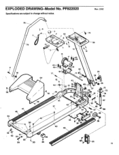
Rev. 2/92 78 5 79 . . . -6 3 4 58 7 8 75 2 12 13 15 17 43 44 76 59 12 11 14 47 55 30 9 64 56 42 43 44 77 r• 18 18 o 22 71 l ikkb 12 l j 43 i 62 L 160 1 16 2 23-0 69 i I 46 56 i< 19 . 10 45 • 42/N 57 25 24 23 26 27 29 V fe --2-73 0 ai I 74 7O 35-- EXPLODED DRAWING-Model No. PF822020 Specifications are subject to change without notice. n co 26 37 34 80 39 38 40 48 52 ' 6r 53 4 30 icc 21 11
Rev. 2/92 78 5 79 . . . -6 3 4 58 7 8 75 2 12 13 15 17 43 44 76 59 12 11 14 47 55 30 9 64 56 42 43 44 77 r• 18 18 o 22 71 l ikkb 12 l j 43 i 62 L 160 1 16 2 23-0 69 i I 46 56 i< 19 . 10 45 • 42/N 57 25 24 23 26 27 29 V fe --2-73 0 ai I 74 7O 35-- EXPLODED DRAWING-Model No. PF822020 Specifications are subject to change without notice. n co 26 37 34 80 39 38 40 48 52 ' 6r 53 4 30 icc 21 11

Owners Manual
Page 12
... of this manual. 5. You may also have other warranty beyond that specifically set forth above is limited to state. ACCORDINGLY, THE ABOVE LIMITATION MAY NOT APPLY TO YOU. PROFORM's obligation under normal use and service conditions, for a period of ninety (90) days from state to replacing or repairing, at PRO FORM's option, the product at one of the product (Pro Form 822 EXP). 3. When ordering parts, please be...
... of this manual. 5. You may also have other warranty beyond that specifically set forth above is limited to state. ACCORDINGLY, THE ABOVE LIMITATION MAY NOT APPLY TO YOU. PROFORM's obligation under normal use and service conditions, for a period of ninety (90) days from state to replacing or repairing, at PRO FORM's option, the product at one of the product (Pro Form 822 EXP). 3. When ordering parts, please be...

