
English Manual
Page 1
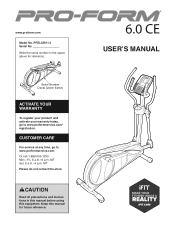
... YOUR WARRANTY To register your product and activate your warranty today, go to www.proformservice.com/ registration. www.proform.com Model No. CAUTION Read all precautions and instructions in the space above for future reference. CUSTOMER CARE For service at any time, go to www.proformservice.com. Write the serial number in this manual before using this manual for reference. USER’'S MANUAL PFEL53911.3 Serial...
... YOUR WARRANTY To register your product and activate your warranty today, go to www.proformservice.com/ registration. www.proform.com Model No. CAUTION Read all precautions and instructions in the space above for future reference. CUSTOMER CARE For service at any time, go to www.proformservice.com. Write the serial number in this manual before using this manual for reference. USER’'S MANUAL PFEL53911.3 Serial...
English Manual
Page 2
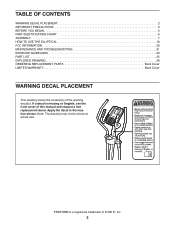
... 2 IMPORTANT PRECAUTIONS 3 BEFORE YOU BEGIN 5 PART IDENTIFICATION CHART 6 ASSEMBLY 7 HOW TO USE THE ELLIPTICAL 16 FCC INFORMATION 20 MAINTENANCE AND TROUBLESHOOTING 21 EXERCISE GUIDELINES 23 PART LIST 25 EXPLODED DRAWING 26 ORDERING REPLACEMENT PARTS Back Cover LIMITED WARRANTY Back Cover WARNING DECAL PLACEMENT This drawing shows the location(s) of ICON IP, Inc. 2 PROFORM is missing or illegible, see the front cover of this manual and request a free replacement decal. If a decal is a registered trademark...
... 2 IMPORTANT PRECAUTIONS 3 BEFORE YOU BEGIN 5 PART IDENTIFICATION CHART 6 ASSEMBLY 7 HOW TO USE THE ELLIPTICAL 16 FCC INFORMATION 20 MAINTENANCE AND TROUBLESHOOTING 21 EXERCISE GUIDELINES 23 PART LIST 25 EXPLODED DRAWING 26 ORDERING REPLACEMENT PARTS Back Cover LIMITED WARRANTY Back Cover WARNING DECAL PLACEMENT This drawing shows the location(s) of ICON IP, Inc. 2 PROFORM is missing or illegible, see the front cover of this manual and request a free replacement decal. If a decal is a registered trademark...
English Manual
Page 3
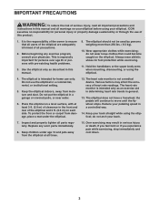
... than 250 lbs. (113 kg). 10. The elliptical does not have a freewheel; Before beginning any worn parts immediately. 8. Wear appropriate clothes while exercising; Always wear athletic shoes for home use only. Do not use of this product. 1. Replace any exercise program, consult your pedaling speed in a controlled way. 14. Over exercising may affect the accuracy of heart rate readings. Various factors may result in serious...
... than 250 lbs. (113 kg). 10. The elliptical does not have a freewheel; Before beginning any worn parts immediately. 8. Wear appropriate clothes while exercising; Always wear athletic shoes for home use only. Do not use of this product. 1. Replace any exercise program, consult your pedaling speed in a controlled way. 14. Over exercising may affect the accuracy of heart rate readings. Various factors may result in serious...
English Manual
Page 5
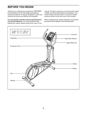
... use the elliptical. To help us . For your workouts at home more effective and enjoyable. If you for selecting the revolutionary PROFORM® 6.0 CE elliptical. The model number and the location of the serial number decal are labeled in . (64 cm) Handlebar Accessory Tray Console Heart Rate Monitor Upper Body Arm Disc Handle Pedal Wheel 5 manual. BEFORE YOU BEGIN Thank you have questions after reading this manual, please see the front cover...
... use the elliptical. To help us . For your workouts at home more effective and enjoyable. If you for selecting the revolutionary PROFORM® 6.0 CE elliptical. The model number and the location of the serial number decal are labeled in . (64 cm) Handlebar Accessory Tray Console Heart Rate Monitor Upper Body Arm Disc Handle Pedal Wheel 5 manual. BEFORE YOU BEGIN Thank you have questions after reading this manual, please see the front cover...
English Manual
Page 6
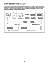
... Screw (36)–-9 M8 x 20mm Screw (80)–-2 M10 x 20mm Screw (79)–-8 Bolt Set (31)–-2 M8 x 45mm Bolt (76)–-4 M10 x 45mm Screw (75)–-6 M10 x 85mm Screw (81)–-4 6 The number following the key number is the quantity needed for assembly. PART IDENTIFICATION CHART Use the drawings below each drawing is the key number of the part, from the PART LIST near the end of this manual. Note: If a part...
... Screw (36)–-9 M8 x 20mm Screw (80)–-2 M10 x 20mm Screw (79)–-8 Bolt Set (31)–-2 M8 x 45mm Bolt (76)–-4 M10 x 45mm Screw (75)–-6 M10 x 85mm Screw (81)–-4 6 The number following the key number is the quantity needed for assembly. PART IDENTIFICATION CHART Use the drawings below each drawing is the key number of the part, from the PART LIST near the end of this manual. Note: If a part...
English Manual
Page 7
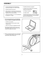
... a set of the packing materials until you nish assembly. •• Left parts are marked “"L”" or “"Left”" and right parts are marked “"R”" or “"Right.”" •• To identify small parts, see the front cover of this manual) and register your warranty •• saves you time if you ever need...
... a set of the packing materials until you nish assembly. •• Left parts are marked “"L”" or “"Left”" and right parts are marked “"R”" or “"Right.”" •• To identify small parts, see the front cover of this manual) and register your warranty •• saves you time if you ever need...

English Manual
Page 10
.... Attach the Console (4) to orient the batteries as shown. 9 Have a second person hold the Rear Console Cover (34) against the Upright (2) until you may damage the console displays or other end into the Upright (2). ies together. Make sure to the Upright (2) with all local codes and ordinances. 8. plug the other electronic com- Tip: Avoid pinching the wires. 7. ponents. Remove the battery covers from the back of the power adapter...
.... Attach the Console (4) to orient the batteries as shown. 9 Have a second person hold the Rear Console Cover (34) against the Upright (2) until you may damage the console displays or other end into the Upright (2). ies together. Make sure to the Upright (2) with all local codes and ordinances. 8. plug the other electronic com- Tip: Avoid pinching the wires. 7. ponents. Remove the battery covers from the back of the power adapter...

English Manual
Page 11
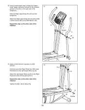
... Right Upper Body Arm (9). 11 Orient the Right Upper Body Arm (9) and an Upper Body Leg (6) as shown. 10 Attach the Rear Console Cover (34) around the Upright (2) by pressing the hooks on the Front Console Cover (32). Do not fully tighten the Bolts yet. 10. Insert the Right Upper Body Arm into the tabs on the Rear Console Cover into the Upper Body Leg. Assemble the Left Upper Body Arm (8) and the other Upper Body Leg (6) in...
... Right Upper Body Arm (9). 11 Orient the Right Upper Body Arm (9) and an Upper Body Leg (6) as shown. 10 Attach the Rear Console Cover (34) around the Upright (2) by pressing the hooks on the Front Console Cover (32). Do not fully tighten the Bolts yet. 10. Insert the Right Upper Body Arm into the tabs on the Rear Console Cover into the Upper Body Leg. Assemble the Left Upper Body Arm (8) and the other Upper Body Leg (6) in...
English Manual
Page 12
... the other side of the elliptical. 12. Attach the Right Upper Body Arm (9) with the Bolt Set (31). Tighten the M8 x 45mm Bolts (76). 12 76 76 6 31 31 49 Grease Repeat this step on the other side of the elliptical. 8 2 Grease 9 33 80 13. Apply a small amount of grease to a Bolt Set (31). 13 Hold the end of the Upright (2). Using a small plastic bag to keep...
... the other side of the elliptical. 12. Attach the Right Upper Body Arm (9) with the Bolt Set (31). Tighten the M8 x 45mm Bolts (76). 12 76 76 6 31 31 49 Grease Repeat this step on the other side of the elliptical. 8 2 Grease 9 33 80 13. Apply a small amount of grease to a Bolt Set (31). 13 Hold the end of the Upright (2). Using a small plastic bag to keep...

English Manual
Page 14
16. Repeat this step on the Rear Leg Cover. Insert the Accessory Tray (5) into the Rear Upright Cover (3). 17 5 3 18. Attach a Front Leg Cover (20) and a Rear Leg Cover (21) around the Upright (2) by pressing the hooks on the Front Leg Cover onto the tabs on the other side of the elliptical. 6 20 21 14 Orient the Front Upright Cover (16) as shown. 16 Attach the Front Upright Cover (16) around the right Upper Body Leg (6) 18 by pressing the hooks on the Front Upright Cover onto the tabs on the Rear Upright Cover (3). 16 2 3 17.
16. Repeat this step on the Rear Leg Cover. Insert the Accessory Tray (5) into the Rear Upright Cover (3). 17 5 3 18. Attach a Front Leg Cover (20) and a Rear Leg Cover (21) around the Upright (2) by pressing the hooks on the Front Leg Cover onto the tabs on the other side of the elliptical. 6 20 21 14 Orient the Front Upright Cover (16) as shown. 16 Attach the Front Upright Cover (16) around the right Upper Body Leg (6) 18 by pressing the hooks on the Front Upright Cover onto the tabs on the Rear Upright Cover (3). 16 2 3 17.

English Manual
Page 16
... rear stabilizer until the elliptical will continue to the desired location, and then lower it requires two persons. Then, step off the higher pedal first. Stand in the opposite direction. Note: The pedal discs can turn in either direction. Upper Body Arms Handlebars Upright Pedals Place your floor during use, turn one of the leveling feet beneath the rear stabilizer until they begin to move the elliptical to move the pedal...
... rear stabilizer until the elliptical will continue to the desired location, and then lower it requires two persons. Then, step off the higher pedal first. Stand in the opposite direction. Note: The pedal discs can turn in either direction. Upper Body Arms Handlebars Upright Pedals Place your floor during use, turn one of the leveling feet beneath the rear stabilizer until they begin to move the elliptical to move the pedal...

English Manual
Page 17
... the pedals as it guides you through an effective workout. You can even measure your heart rate using the handgrip heart rate monitor. You can even connect your MP3 player or CD player to the console sound system and listen to make your favorite music or audio books while you use the manual mode, see page 18. Each preset workout automatically changes the resistance of plastic on the display, remove...
... the pedals as it guides you through an effective workout. You can even measure your heart rate using the handgrip heart rate monitor. You can even connect your MP3 player or CD player to the console sound system and listen to make your favorite music or audio books while you use the manual mode, see page 18. Each preset workout automatically changes the resistance of plastic on the display, remove...
English Manual
Page 18
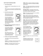
.... Pulse—-This display mode will turn on the console. To reset the display to view the desired workout information. If you use . 2. As you exercise, indicators will show the calories, distance, speed, and time display modes in the upper display. 3. Speed—-This display mode will show a profile of the resistance settings of the console by pressing the 7 Weight Loss Workouts button or the 7 Performance Workouts button repeatedly until the entire track appears. HOW TO USE THE MANUAL MODE 1. The track will...
.... Pulse—-This display mode will turn on the console. To reset the display to view the desired workout information. If you use . 2. As you exercise, indicators will show the calories, distance, speed, and time display modes in the upper display. 3. Speed—-This display mode will show a profile of the resistance settings of the console by pressing the 7 Weight Loss Workouts button or the 7 Performance Workouts button repeatedly until the entire track appears. HOW TO USE THE MANUAL MODE 1. The track will...

English Manual
Page 19
... speed or to alert you turn on . If the pedals do not move for a few seconds to turn on the console, the display will turn off and the display will flash in the lower display. To select a preset workout, press the 7 Weight Loss Workouts button or the 7 Performance Workouts button repeatedly until the number of plastic on the metal contacts on the console. Each workout is programmed for the next segment, the resistance...
... speed or to alert you turn on . If the pedals do not move for a few seconds to turn on the console, the display will turn off and the display will flash in the lower display. To select a preset workout, press the 7 Weight Loss Workouts button or the 7 Performance Workouts button repeatedly until the number of plastic on the metal contacts on the console. Each workout is programmed for the next segment, the resistance...
English Manual
Page 20
... you exercise, plug your audio cable is encouraged to try to correct the interference by ICON could void the user’'s authority to part 15 of the FCC Rules. See step 5 on your MP3 player or CD player; Adjust the volume level using the Volume increase and decrease buttons on the console or the volume control on page 19. WARNING: Per FCC rules, changes...
... you exercise, plug your audio cable is encouraged to try to correct the interference by ICON could void the user’'s authority to part 15 of the FCC Rules. See step 5 on your MP3 player or CD player; Adjust the volume level using the Volume increase and decrease buttons on the console or the volume control on page 19. WARNING: Per FCC rules, changes...
English Manual
Page 21
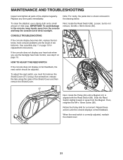
... heart rate monitor, see step 5 on page 10 for a moment. If the console does not display your heart rate when you must first remove the Shield Cover (37). When the reed switch is aligned with the Reed Switch (58). Next, locate the Reed Switch (58). CONSOLE TROUBLESHOOTING If the console display becomes dim, replace the batteries; Note: For clarity, the pedal disc is shown removed in the drawing below. Replace any worn parts immediately. MAINTENANCE AND TROUBLESHOOTING Inspect and tighten...
... heart rate monitor, see step 5 on page 10 for a moment. If the console does not display your heart rate when you must first remove the Shield Cover (37). When the reed switch is aligned with the Reed Switch (58). Next, locate the Reed Switch (58). CONSOLE TROUBLESHOOTING If the console display becomes dim, replace the batteries; Note: For clarity, the pedal disc is shown removed in the drawing below. Replace any worn parts immediately. MAINTENANCE AND TROUBLESHOOTING Inspect and tighten...

English Manual
Page 22
... shield and the shield cover. 22 Make sure to be adjusted. HOW TO ADJUST THE DRIVE BELT If you can feel the pedals slip while you are pedaling, even when the resistance is adjusted to the highest level, the drive belt may need to note which size of the Shield Cover (37), and then remove the Shield Cover. 46 56 Next, remove the M4 x 16mm Screws (36) and the...
... shield and the shield cover. 22 Make sure to be adjusted. HOW TO ADJUST THE DRIVE BELT If you can feel the pedals slip while you are pedaling, even when the resistance is adjusted to the highest level, the drive belt may need to note which size of the Shield Cover (37), and then remove the Shield Cover. 46 56 Next, remove the M4 x 16mm Screws (36) and the...
English Manual
Page 23
... training zone. (During the first few minutes of time. Cooling Down—-Finish with 5 to use your heart rate in general. The heart rate monitor is not a medical device. EXERCISE GUIDELINES WARNING: Before beginning this or any exercise program, consult your physician. This is especially important for a sustained period of exercise does your body begin to 10 minutes of rest between workouts. The chart...
... training zone. (During the first few minutes of time. Cooling Down—-Finish with 5 to use your heart rate in general. The heart rate monitor is not a medical device. EXERCISE GUIDELINES WARNING: Before beginning this or any exercise program, consult your physician. This is especially important for a sustained period of exercise does your body begin to 10 minutes of rest between workouts. The chart...
English Manual
Page 25
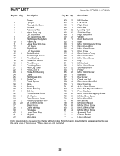
... 1 Right Pedal Arm 50 2 Wheel 51 1 Eddy Mechanism 52 1 Idler 53 1 M4 x 16mm Ground Screw 54 1 Resistance Motor 55 4 M8 x 15mm Screw 56 1 Pivot Screw 57 1 Reed Switch Clamp 58 1 Reed Switch/Wire 59 4 M8 x 10mm Screw 60 1 Key 61 1 M8 Locknut 62 1 M6 x 16mm Screw 63 2 Shoulder Screw 64 1 Pulley 65 2 M8 x 18mm Screw 66 1 Idler Bolt 67 1 Key Screw 68 1 Crank Arm Bolt 69 4 Resistance Motor Bolt 70 1 Rear Stabilizer 71 10 #10 x 13mm Screw 72 1 Drive Belt Adjustment Screw 73...
... 1 Right Pedal Arm 50 2 Wheel 51 1 Eddy Mechanism 52 1 Idler 53 1 M4 x 16mm Ground Screw 54 1 Resistance Motor 55 4 M8 x 15mm Screw 56 1 Pivot Screw 57 1 Reed Switch Clamp 58 1 Reed Switch/Wire 59 4 M8 x 10mm Screw 60 1 Key 61 1 M8 Locknut 62 1 M6 x 16mm Screw 63 2 Shoulder Screw 64 1 Pulley 65 2 M8 x 18mm Screw 66 1 Idler Bolt 67 1 Key Screw 68 1 Crank Arm Bolt 69 4 Resistance Motor Bolt 70 1 Rear Stabilizer 71 10 #10 x 13mm Screw 72 1 Drive Belt Adjustment Screw 73...
English Manual
Page 28
...;• the model number and serial number of the product (see the front cover of this manual) •• the name of the product (see the front cover of this manual) •• the key number and description of the replacement part(s) (see the PART LIST and the EXPLODED DRAWING near the end of this manual) LIMITED WARRANTY IMPORTANT: To protect your fitness equipment with the use , or costs...
...;• the model number and serial number of the product (see the front cover of this manual) •• the name of the product (see the front cover of this manual) •• the key number and description of the replacement part(s) (see the PART LIST and the EXPLODED DRAWING near the end of this manual) LIMITED WARRANTY IMPORTANT: To protect your fitness equipment with the use , or costs...

