
English Manual
Page 7
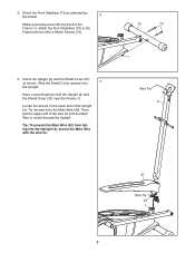
... and the Shield Cover (37) near the Frame (1). Tie the wire tie to the Frame with the wire tie. 73 74 1 Wire Tie 2 37 Wire Tie 42 1 7 Locate the wire tie in the lower end of the wire tie until the Main Wire is routed through the Upright. Then, pull the upper end of ...3 While a second person lifts the front of the Frame (1), attach the Front Stabilizer (73) to the Main Wire (42). Tip: To prevent the Main Wire (42) from falling into the Upright (2), secure the Main Wire with two M10 x 85mm Screws (74). 4. 3. Slide the Shield Cover upward onto 4 the Upright. Orient ...
... and the Shield Cover (37) near the Frame (1). Tie the wire tie to the Frame with the wire tie. 73 74 1 Wire Tie 2 37 Wire Tie 42 1 7 Locate the wire tie in the lower end of the wire tie until the Main Wire is routed through the Upright. Then, pull the upper end of ...3 While a second person lifts the front of the Frame (1), attach the Front Stabilizer (73) to the Main Wire (42). Tip: To prevent the Main Wire (42) from falling into the Upright (2), secure the Main Wire with two M10 x 85mm Screws (74). 4. 3. Slide the Shield Cover upward onto 4 the Upright. Orient ...
English Manual
Page 8
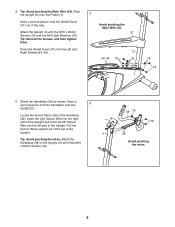
...(2) onto the Frame (1). Press the Shield Cover (37) into the left Sensor Wire into the Left and Right Shields (44, 45). 5 Avoid pinching the Main Wire (42) 37 2 44, 45 79 78 1 78 79 6. Pull the Sensor Wires upward out of the top of the way. 5. Attach the Upright (2) with ...Upright and insert the left side of the Upright. Have a second person hold the Shield Cover (37) out of the Upright. 2 Tip: Avoid pinching the wires. Attach the Handlebar (39) to the Upright (2) with five M10 x 20mm Screws (79) and five M10 Split Washers (78). Have a second person hold...
...(2) onto the Frame (1). Press the Shield Cover (37) into the left Sensor Wire into the Left and Right Shields (44, 45). 5 Avoid pinching the Main Wire (42) 37 2 44, 45 79 78 1 78 79 6. Pull the Sensor Wires upward out of the top of the way. 5. Attach the Upright (2) with ...Upright and insert the left side of the Upright. Have a second person hold the Shield Cover (37) out of the Upright. 2 Tip: Avoid pinching the wires. Attach the Handlebar (39) to the Upright (2) with five M10 x 20mm Screws (79) and five M10 Split Washers (78). Have a second person hold...
English Manual
Page 9
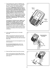
...the power adapter into an outlet installed in accordance with four M4 x 16mm Screws (53). Battery Cover 4 Battery Cover Receptacle 4 Avoid pinching the wires 42 2 28 53 9. IMPORTANT: If the Console has been exposed to cold temperatures, allow it to warm to the Upright (2) with all ... compartment on the Console to the Main Wire (42) and to the Sensor Wires (28). Untie and discard the wire tie on the Main Wire (42). 8 While a second person holds the Console (4) near the Upright (2), connect the wires on the console; Insert the excess wire into the Upright (2) or into the ...
...the power adapter into an outlet installed in accordance with four M4 x 16mm Screws (53). Battery Cover 4 Battery Cover Receptacle 4 Avoid pinching the wires 42 2 28 53 9. IMPORTANT: If the Console has been exposed to cold temperatures, allow it to warm to the Upright (2) with all ... compartment on the Console to the Main Wire (42) and to the Sensor Wires (28). Untie and discard the wire tie on the Main Wire (42). 8 While a second person holds the Console (4) near the Upright (2), connect the wires on the console; Insert the excess wire into the Upright (2) or into the ...
English Manual
Page 25
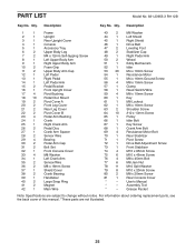
... Cover 22 2 Pivot Cover B 23 4 Pedal Arm Bushing 24 1 Crank 25 1 Right Crank Arm 26 2 Pedal Disc 27 1 Crank Arm Spacer 28 2 Sensor Wire 29 4 Bearing 30 2 Pedal Arm Cap 31 2 Bolt Set 32 1 Front Console Cover 33 4 M8 Washer 34 1 Left Crank Arm 35 2 Sensor... 52 1 Idler 53 20 M4 x 16mm Screw 54 1 Resistance Motor 55 1 M4 x 16mm Ground Screw 56 4 M8 x 15mm Screw 57 1 Clamp 58 1 Reed Switch/Wire 59 4 M8 x 10mm Screw 60 1 Key 61 1 M8 Locknut 62 1 M6 x 16mm Screw 63 2 Shoulder Screw 64 10 #10 x 13mm Screw 65 1 Pulley 66...
... Cover 22 2 Pivot Cover B 23 4 Pedal Arm Bushing 24 1 Crank 25 1 Right Crank Arm 26 2 Pedal Disc 27 1 Crank Arm Spacer 28 2 Sensor Wire 29 4 Bearing 30 2 Pedal Arm Cap 31 2 Bolt Set 32 1 Front Console Cover 33 4 M8 Washer 34 1 Left Crank Arm 35 2 Sensor... 52 1 Idler 53 20 M4 x 16mm Screw 54 1 Resistance Motor 55 1 M4 x 16mm Ground Screw 56 4 M8 x 15mm Screw 57 1 Clamp 58 1 Reed Switch/Wire 59 4 M8 x 10mm Screw 60 1 Key 61 1 M8 Locknut 62 1 M6 x 16mm Screw 63 2 Shoulder Screw 64 10 #10 x 13mm Screw 65 1 Pulley 66...

