

Uk Manual
Page 2
... WARNING DECAL PLACEMENT 2 IMPORTANT PRECAUTIONS 3 BEFORE YOU BEGIN 5 ASSEMBLY 6 OPERATION AND ADJUSTMENT 13 HOW TO FOLD AND MOVE THE TREADMILL 20 TROUBLESHOOTING 22 EXERCISE GUIDELINES 25 PART LIST 26 EXPLODED DRAWING 28 ORDERING REPLACEMENT PARTS Back Cover RECYCLING INFORMATION Back Cover WARNING DECAL ...PLACEMENT The decals shown here have been applied in the location shown. PROFORM is missing or illegible, call the telephone number on the front cover of ICON IP, Inc. 2 If a decal is a...
... WARNING DECAL PLACEMENT 2 IMPORTANT PRECAUTIONS 3 BEFORE YOU BEGIN 5 ASSEMBLY 6 OPERATION AND ADJUSTMENT 13 HOW TO FOLD AND MOVE THE TREADMILL 20 TROUBLESHOOTING 22 EXERCISE GUIDELINES 25 PART LIST 26 EXPLODED DRAWING 28 ORDERING REPLACEMENT PARTS Back Cover RECYCLING INFORMATION Back Cover WARNING DECAL ...PLACEMENT The decals shown here have been applied in the location shown. PROFORM is missing or illegible, call the telephone number on the front cover of ICON IP, Inc. 2 If a decal is a...

Uk Manual
Page 3
...is especially important for personal injury or property damage sustained by persons weighing 286 lbs. (130 kg) or less. 13. Do not place the treadmill on a level surface, with bare feet, wearing only stockings, or in small increments to the fuse carrier. Keep the power cord away from moisture... the accuracy of all users of this manual and all times. 8. It is the responsibility of the owner to the off position when the treadmill is intended only as described. 4. Do not wear loose clothes that all warnings and precautions. 12. Always wear athletic shoes. The pulse sensor...
...is especially important for personal injury or property damage sustained by persons weighing 286 lbs. (130 kg) or less. 13. Do not place the treadmill on a level surface, with bare feet, wearing only stockings, or in small increments to the fuse carrier. Keep the power cord away from moisture... the accuracy of all users of this manual and all times. 8. It is the responsibility of the owner to the off position when the treadmill is intended only as described. 4. Do not wear loose clothes that all warnings and precautions. 12. Always wear athletic shoes. The pulse sensor...

Uk Manual
Page 4
.... DANGER: 24. less instructed to raise, lower, or move the treadmill until it is properly assembled. (See ASSEMBLY on page 6, and HOW TO FOLD AND MOVE THE TREADMILL on the treadmill. 23. Do not use this treadmill in this manual. 20. Inspect and properly tighten all parts of the... treadmill regularly. Never remove the motor hood un- Servicing other than the procedures in a ...
.... DANGER: 24. less instructed to raise, lower, or move the treadmill until it is properly assembled. (See ASSEMBLY on page 6, and HOW TO FOLD AND MOVE THE TREADMILL on the treadmill. 23. Do not use this treadmill in this manual. 20. Inspect and properly tighten all parts of the... treadmill regularly. Never remove the motor hood un- Servicing other than the procedures in a ...

Uk Manual
Page 5
... questions after read this manual. ing this manual, please see the front cover of other treadmills. The PF 3.6 treadmill offers an impressive array of this manual carefully before contacting us assist you for selecting the revolutionary PROFORM® PF 3.6 treadmill. To help us (see the front cover of features designed to make your benefit...
... questions after read this manual. ing this manual, please see the front cover of other treadmills. The PF 3.6 treadmill offers an impressive array of this manual carefully before contacting us assist you for selecting the revolutionary PROFORM® PF 3.6 treadmill. To help us (see the front cover of features designed to make your benefit...

Uk Manual
Page 6
... of lubricant may be included. If there is completed. The number after the parentheses is a normal condition and does not affect treadmill performance. Set the treadmill in parentheses below to see if it is the key number of the part, from the Base (85). Do not dispose of... on the other side of the walking belt or the shipping carton. Use the drawings below each drawing is preattached to the top of the treadmill. Extra hardware may be assembled. M4.2 x 19mm Screw (1)-4 M4.2 x 25mm Screw (2)-4 M4 x 20mm Screw (3)-2 3/8" Jamnut (31)-3 Base Pad Spacer (104)-2 M4.2...
... of lubricant may be included. If there is completed. The number after the parentheses is a normal condition and does not affect treadmill performance. Set the treadmill in parentheses below to see if it is the key number of the part, from the Base (85). Do not dispose of... on the other side of the walking belt or the shipping carton. Use the drawings below each drawing is preattached to the top of the treadmill. Extra hardware may be assembled. M4.2 x 19mm Screw (1)-4 M4.2 x 25mm Screw (2)-4 M4 x 20mm Screw (3)-2 3/8" Jamnut (31)-3 Base Pad Spacer (104)-2 M4.2...
Uk Manual
Page 7
... in the Base, and use the tie to the Base (85). Attach a Wheel (86) with the M10 x 50mm Bolt 3 (4) and M10 Nut (33) that the treadmill is more stable; Cut the tie securing the Upright Wire (77) to pull the Upright Wire out of a second person, carefully tip the...
... in the Base, and use the tie to the Base (85). Attach a Wheel (86) with the M10 x 50mm Bolt 3 (4) and M10 Nut (33) that the treadmill is more stable; Cut the tie securing the Upright Wire (77) to pull the Upright Wire out of a second person, carefully tip the...

Uk Manual
Page 9
... overtighten the Nut; Hold the Left Upright Spacer and the Left Upright against the Base (85). With the help of a second person, carefully tip the treadmill onto its right side. Finger tighten the M10 x 96mm Bolts (5); Remove the four M4.2 x 16mm Screws (12) and the two M5 x 15mm Screws (64). ...fully tighten the Bolts yet. Attach a Wheel (86) with a Base Pad Spacer (104) and an M4.2 x 25mm Screw (2). Partially fold the Frame (48) so the treadmill is flat on a soft surface to the Base (85) in step 1. the Wheel must turn freely. 6 81 2 85 48 127 104 86 2 81 33 7. Press...
... overtighten the Nut; Hold the Left Upright Spacer and the Left Upright against the Base (85). With the help of a second person, carefully tip the treadmill onto its right side. Finger tighten the M10 x 96mm Bolts (5); Remove the four M4.2 x 16mm Screws (12) and the two M5 x 15mm Screws (64). ...fully tighten the Bolts yet. Attach a Wheel (86) with a Base Pad Spacer (104) and an M4.2 x 25mm Screw (2). Partially fold the Frame (48) so the treadmill is flat on a soft surface to the Base (85) in step 1. the Wheel must turn freely. 6 81 2 85 48 127 104 86 2 81 33 7. Press...

Uk Manual
Page 12
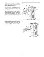
...). Keep the included hex keys in a secure place; Identify the Latch Assembly (72). the large hex key is locked into the hole. Pull on the treadmill decals, remove the plastic. Attach the Latch Bracket (71) to align the Latch Assembly with a 3/8" x 2" Bolt (27) and a 3/8" Jamnut (31). Lower the Frame (...48) (see pages 23 and 24). 12 To protect the floor or carpet, place a mat under the treadmill. 13. Make sure that the sleeve has been slid over the indicated hole and that all parts are sheets of the Latch Assembly (72) to...
...). Keep the included hex keys in a secure place; Identify the Latch Assembly (72). the large hex key is locked into the hole. Pull on the treadmill decals, remove the plastic. Attach the Latch Bracket (71) to align the Latch Assembly with a 3/8" x 2" Bolt (27) and a 3/8" Jamnut (31). Lower the Frame (...48) (see pages 23 and 24). 12 To protect the floor or carpet, place a mat under the treadmill. 13. Make sure that the sleeve has been slid over the indicated hole and that all parts are sheets of the Latch Assembly (72) to...

Uk Manual
Page 13
...power cord into an appropriate outlet that the adapter cover is properly installed and earthed in accordance with RCD-equipped outlets. Important: The treadmill is damaged, it must be replaced with a manufacturer-recommended power cord. Do not modify the plug provided with high-performance lubricant....having an equipment-earthing conductor and an earthing plug. See drawing 2. Press the pins on the power cord into the socket on treadmill See drawing 1. Close the adapter cover over the end of electric shock. IMPORTANT: Never apply silicone spray or other substances to ...
...power cord into an appropriate outlet that the adapter cover is properly installed and earthed in accordance with RCD-equipped outlets. Important: The treadmill is damaged, it must be replaced with a manufacturer-recommended power cord. Do not modify the plug provided with high-performance lubricant....having an equipment-earthing conductor and an earthing plug. See drawing 2. Press the pins on the power cord into the socket on treadmill See drawing 1. Close the adapter cover over the end of electric shock. IMPORTANT: Never apply silicone spray or other substances to ...

Uk Manual
Page 14
...instructions in cally controls the speed and incline of the console, follow the steps beginning on When you use the manual mode of the treadmill as either miles or kilometers. surement, see In addition, the console features five classic work - You can even measure your workouts more... effec- To prevent damage speed and incline of the treadmill with the touch of out, see features designed to the walking platform, wear clean athletic shoes button. CONSOLE DIAGRAM Key Clip FEATURES OF...
...instructions in cally controls the speed and incline of the console, follow the steps beginning on When you use the manual mode of the treadmill as either miles or kilometers. surement, see In addition, the console features five classic work - You can even measure your workouts more... effec- To prevent damage speed and incline of the treadmill with the touch of out, see features designed to the walking platform, wear clean athletic shoes button. CONSOLE DIAGRAM Key Clip FEATURES OF...

Uk Manual
Page 15
... you hold down a button, the speed setting will light. If the displays remain lit, see THE INFORMATION MODE on the foot rails of the treadmill. Then, insert the key into the console. Start the walking belt. If you plug in the display. Select the manual mode. Switch the circuit... off the demo mode, hold down the Stop button for a few steps backward; Note: After you press a button, it may take a moment for the treadmill to reach the selected incline setting. 15 Note: After you press a button, it may become damaged. 1. If a preset workout has been selected, remove the...
... you hold down a button, the speed setting will light. If the displays remain lit, see THE INFORMATION MODE on the foot rails of the treadmill. Then, insert the key into the console. Start the walking belt. If you plug in the display. Select the manual mode. Switch the circuit... off the demo mode, hold down the Stop button for a few steps backward; Note: After you press a button, it may take a moment for the treadmill to reach the selected incline setting. 15 Note: After you press a button, it may become damaged. 1. If a preset workout has been selected, remove the...

Uk Manual
Page 16
...on the pulse bar. In addition, make sure that you exercise, the lower left display- As you have burned and the speed of the treadmill to the "off circuit breaker to the lowest setting. To measure your heart rate, stand on the foot rails and hold the contacts for about... not be at the lowest setting or you are finished using the handgrip pulse sensor, remove the sheets of the elapsed time. Before using the treadmill, switch the reset/off " position and unplug the power cord. Note: When a workout is detected, a heart symbol in succession. The lower right display-...
...on the pulse bar. In addition, make sure that you exercise, the lower left display- As you have burned and the speed of the treadmill to the "off circuit breaker to the lowest setting. To measure your heart rate, stand on the foot rails and hold the contacts for about... not be at the lowest setting or you are finished using the handgrip pulse sensor, remove the sheets of the elapsed time. Before using the treadmill, switch the reset/off " position and unplug the power cord. Note: When a workout is detected, a heart symbol in succession. The lower right display-...

Uk Manual
Page 17
..., remove the key from the console. The walking belt will automatically adjust to the first speed and incline settings of the workout begins, the treadmill will then slow to flash. To restart the workout, press the Start button or the Speed increase button. Press the Start button or the ...A CLASSIC WORKOUT 1. Note: The number and profile of each segment, a series of tones will sound and the next segment of the workout begins, the treadmill will flash in the display and the last segment ends. To stop . The walking belt will begin walking. 5. Note: The same speed setting and/or...
..., remove the key from the console. The walking belt will automatically adjust to the first speed and incline settings of the workout begins, the treadmill will then slow to flash. To restart the workout, press the Start button or the Speed increase button. Press the Start button or the ...A CLASSIC WORKOUT 1. Note: The number and profile of each segment, a series of tones will sound and the next segment of the workout begins, the treadmill will flash in the display and the last segment ends. To stop . The walking belt will begin walking. 5. Note: The same speed setting and/or...

Uk Manual
Page 18
...the workout, press the Start button or the Speed increase button. See step 7 on page 15. At the end of the workout begins, the treadmill will begin walking. To select a weight loss workout, press the Weight Loss Workouts button repeatedly. Enter your progress with the displays. Note: The ... button to a stop the workout at 2 km/h. A moment after you . 2. Hold the handrails and begin to alert you press the button, the treadmill will begin to the first speed and incline settings of calories printed on the profiles on your heart rate if desired. Each workout is listed...
...the workout, press the Start button or the Speed increase button. See step 7 on page 15. At the end of the workout begins, the treadmill will begin walking. To select a weight loss workout, press the Weight Loss Workouts button repeatedly. Enter your progress with the displays. Note: The ... button to a stop the workout at 2 km/h. A moment after you . 2. Hold the handrails and begin to alert you press the button, the treadmill will begin to the first speed and incline settings of calories printed on the profiles on your heart rate if desired. Each workout is listed...

Uk Manual
Page 19
...increase button to be shown: An "E" for English miles or an "M" for metric kilometers will show the total number of miles (or kilometers) that the treadmill has been used. However, when you plug in a store. To select the information mode, hold down the Stop button while inserting the key into the... normally when you remove the key, the displays will remain lit, although the buttons will show the total number of hours the treadmill has been used if the treadmill is displayed in the power cord, switch the reset/off the display demo mode. To turn on or off the demo mode...
...increase button to be shown: An "E" for English miles or an "M" for metric kilometers will show the total number of miles (or kilometers) that the treadmill has been used. However, when you plug in a store. To select the information mode, hold down the Stop button while inserting the key into the... normally when you remove the key, the displays will remain lit, although the buttons will show the total number of hours the treadmill has been used if the treadmill is displayed in the power cord, switch the reset/off the display demo mode. To turn on or off the demo mode...

Uk Manual
Page 20
...the storage position. Make sure that the latch knob is locked in temperatures above . Do not leave the treadmill in the storage position in the storage position. 1. Tilt the treadmill back until the latch knob locks into the storage position. Frame Handrail Wheels 20 Base Remove the key ...straight as described above 85° F (30° C). Raise the frame until it . Frame Latch Knob HOW TO MOVE THE TREADMILL Before moving the treadmill. Never move the treadmill. 1. CAUTION: You must be able to safely lift 45 lbs. (20 kg) to the desired location. Do not attempt to ...
...the storage position. Make sure that the latch knob is locked in temperatures above . Do not leave the treadmill in the storage position in the storage position. 1. Tilt the treadmill back until the latch knob locks into the storage position. Frame Handrail Wheels 20 Base Remove the key ...straight as described above 85° F (30° C). Raise the frame until it . Frame Latch Knob HOW TO MOVE THE TREADMILL Before moving the treadmill. Never move the treadmill. 1. CAUTION: You must be able to safely lift 45 lbs. (20 kg) to the desired location. Do not attempt to ...

Uk Manual
Page 21
Hold the metal frame firmly with your back straight. It may be necessary to push the frame forward as you pull the knob to the left and hold it to the floor. Bend your legs and keep your right hand. Latch Knob 21 Pivot the frame downward and release the latch knob. 2. Pull the latch knob to the floor. HOW TO LOWER THE TREADMILL FOR USE 1. Hold the upper end of the treadmill with both hands and lower it . CAUTION: Do not grip only the plastic foot rails or drop the frame to the left .
Hold the metal frame firmly with your back straight. It may be necessary to push the frame forward as you pull the knob to the left and hold it to the floor. Bend your legs and keep your right hand. Latch Knob 21 Pivot the frame downward and release the latch knob. 2. Pull the latch knob to the floor. HOW TO LOWER THE TREADMILL FOR USE 1. Hold the upper end of the treadmill with both hands and lower it . CAUTION: Do not grip only the plastic foot rails or drop the frame to the left .

Uk Manual
Page 22
...plugged in . With the key in . Remove the key from the console. If an extension cord is needed , please see page 13). Important: The treadmill is no longer than 5 ft. (1.5 m). Check the reset/off during use only a 3-conductor, 14-gauge (1 mm2 ) cord that the power cord ...steps listed. While the incline is plugged into a properly earthed outlet (see the front cover of this manual. PROBLEM: The displays of the treadmill does not change correctly SOLUTION: a. Make sure that is not compatible with RCD-equipped outlets. c Tripped Reset PROBLEM: The power turns off ...
...plugged in . With the key in . Remove the key from the console. If an extension cord is needed , please see page 13). Important: The treadmill is no longer than 5 ft. (1.5 m). Check the reset/off during use only a 3-conductor, 14-gauge (1 mm2 ) cord that the power cord ...steps listed. While the incline is plugged into a properly earthed outlet (see the front cover of this manual. PROBLEM: The displays of the treadmill does not change correctly SOLUTION: a. Make sure that is not compatible with RCD-equipped outlets. c Tripped Reset PROBLEM: The power turns off ...

Uk Manual
Page 23
... necessary, loosen the M4.2 x 19mm Screw (1), move the Reed Switch slightly, and then retighten the Screw. Reattach the Hood (not shown), and run the treadmill for a few minutes. Using the hex key, turn both rear roller bolts counterclockwise, 1/4 of the walking belt 2 to be able to 7 cm) off ... platform. Locate the Reed Switch (54) and the Magnet (42) on the left side of this manual. 23 Make sure that is overtightened, treadmill performance may decrease and the walking belt may become damaged. If the displays are still lit, see the front cover of the Pulley (44). b....
... necessary, loosen the M4.2 x 19mm Screw (1), move the Reed Switch slightly, and then retighten the Screw. Reattach the Hood (not shown), and run the treadmill for a few minutes. Using the hex key, turn both rear roller bolts counterclockwise, 1/4 of the walking belt 2 to be able to 7 cm) off ... platform. Locate the Reed Switch (54) and the Magnet (42) on the left side of this manual. 23 Make sure that is overtightened, treadmill performance may decrease and the walking belt may become damaged. If the displays are still lit, see the front cover of the Pulley (44). b....

Uk Manual
Page 24
Then, plug in the power cord, insert the key, and run the treadmill for a few minutes. b. rectly tightened, you should be able to lift each side of a turn both rear roller bolts clock- ing belt is cor- wise, 1/4 ...of the walking belt 2 to 3 in the power cord, insert the key, and carefully walk on the treadmill for a few minutes. When the walking belt is centered. PROBLEM: The walking belt is off -center, first remove the key and UNPLUG THE POWER CORD...
Then, plug in the power cord, insert the key, and run the treadmill for a few minutes. b. rectly tightened, you should be able to lift each side of a turn both rear roller bolts clock- ing belt is cor- wise, 1/4 ...of the walking belt 2 to 3 in the power cord, insert the key, and carefully walk on the treadmill for a few minutes. When the walking belt is centered. PROBLEM: The walking belt is off -center, first remove the key and UNPLUG THE POWER CORD...


