
English Manual
Page 1
... STORE; USER'S MANUAL MT ON THE WEB: www.proformservice.com CAUTION Read all precautions and instructions in the space above ) before using this manual for reference. MT Sat. 8 a.m.-4 p.m. Keep this equipment. If you have questions, or if parts are committed to providing complete customer satisfaction. PFEX02908.0 Serial No. Write the serial number in this manual before contacting us: CALL TOLL-FREE: 1-888...
... STORE; USER'S MANUAL MT ON THE WEB: www.proformservice.com CAUTION Read all precautions and instructions in the space above ) before using this manual for reference. MT Sat. 8 a.m.-4 p.m. Keep this equipment. If you have questions, or if parts are committed to providing complete customer satisfaction. PFEX02908.0 Serial No. Write the serial number in this manual before contacting us: CALL TOLL-FREE: 1-888...
English Manual
Page 2
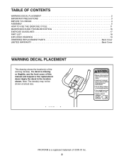
... the location shown. PROFORM is missing or illegible, see the front cover of ICON IP, Inc. 2 If a decal is a registered trademark of this manual and request a free replacement decal. TABLE OF CONTENTS WARNING DECAL PLACEMENT 2 IMPORTANT PRECAUTIONS 3 BEFORE YOU BEGIN 4 ASSEMBLY 5 HOW TO USE THE EXERCISE CYCLE 11 MAINTENANCE AND TROUBLESHOOTING 16 EXERCISE GUIDELINES 17 PART LIST 18 EXPLODED DRAWING 19 ORDERING REPLACEMENT PARTS Back Cover LIMITED WARRANTY Back Cover WARNING...
... the location shown. PROFORM is missing or illegible, see the front cover of ICON IP, Inc. 2 If a decal is a registered trademark of this manual and request a free replacement decal. TABLE OF CONTENTS WARNING DECAL PLACEMENT 2 IMPORTANT PRECAUTIONS 3 BEFORE YOU BEGIN 4 ASSEMBLY 5 HOW TO USE THE EXERCISE CYCLE 11 MAINTENANCE AND TROUBLESHOOTING 16 EXERCISE GUIDELINES 17 PART LIST 18 EXPLODED DRAWING 19 ORDERING REPLACEMENT PARTS Back Cover LIMITED WARRANTY Back Cover WARNING...
English Manual
Page 3
... and properly tighten all warnings on your exercise cycle at least 2 ft. (0.6 m) of clearance around the exercise cycle. 5. Wear appropriate exercise clothes while exercising; When adjusting the seat, insert the adjustment knob into one of heart rate readings. The pulse sensor is intended only as described in this manual. 3 Before beginning any worn parts immediately. 6. The pulse sensor is not a medical device. If you stop exercising, allow the pedals to...
... and properly tighten all warnings on your exercise cycle at least 2 ft. (0.6 m) of clearance around the exercise cycle. 5. Wear appropriate exercise clothes while exercising; When adjusting the seat, insert the adjustment knob into one of heart rate readings. The pulse sensor is intended only as described in this manual. 3 Before beginning any worn parts immediately. 6. The pulse sensor is not a medical device. If you stop exercising, allow the pedals to...
English Manual
Page 4
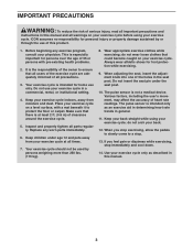
... the product model number and serial number before you use the exercise cycle. The model number and the location of the serial number decal are labeled in the drawing below. Handgrip Pulse Sensor Water Bottle Holder* Seat Seat Knob Seat Post Knob Console Transport Wheel Pedal/Strap *Water bottle is an effective exercise for selecting the revolutionary PROFORM® 180 UR exercise cycle. If you have questions after reading this manual, please see the front cover of features...
... the product model number and serial number before you use the exercise cycle. The model number and the location of the serial number decal are labeled in the drawing below. Handgrip Pulse Sensor Water Bottle Holder* Seat Seat Knob Seat Post Knob Console Transport Wheel Pedal/Strap *Water bottle is an effective exercise for selecting the revolutionary PROFORM® 180 UR exercise cycle. If you have questions after reading this manual, please see the front cover of features...
English Manual
Page 5
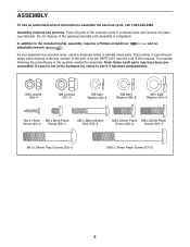
... Patch Screw (67)-2 5 ASSEMBLY To hire an authorized service technician to the included tool(s), assembly requires a Phillips screwdriver adjustable wrench . Do not dispose of the exercise cycle in parentheses below to see if it has been preassembled. The number following the parentheses is the key number of the part, from the PART LIST near the end of this manual. In addition to assemble the exercise...
... Patch Screw (67)-2 5 ASSEMBLY To hire an authorized service technician to the included tool(s), assembly requires a Phillips screwdriver adjustable wrench . Do not dispose of the exercise cycle in parentheses below to see if it has been preassembled. The number following the parentheses is the key number of the part, from the PART LIST near the end of this manual. In addition to assemble the exercise...

English Manual
Page 6
... with two M10 x 54mm Patch Screws (33) and two M10 Split Washers (34). While another person lifts the rear of the Frame (1), attach the Rear Stabilizer to the Frame 3 with two 2 4 M4 x 16mm Screws (40). Attach the Right Cap with two M10 x 78mm Patch Screws (67) and two M10 Split ...person lifts the front of the Rear Stabilizer (14). Attach the Left Cap (4) in the same way. 14 73 40 3. Orient the Rear Stabilizer (14) so that the indicated holes are at the bottom. Holes 34 33 1 14 Holes 2. To make assembly easier, read the 1 information on page 5 before you begin...
... with two M10 x 54mm Patch Screws (33) and two M10 Split Washers (34). While another person lifts the rear of the Frame (1), attach the Rear Stabilizer to the Frame 3 with two 2 4 M4 x 16mm Screws (40). Attach the Right Cap with two M10 x 78mm Patch Screws (67) and two M10 Split ...person lifts the front of the Rear Stabilizer (14). Attach the Left Cap (4) in the same way. 14 73 40 3. Orient the Rear Stabilizer (14) so that the indicated holes are at the bottom. Holes 34 33 1 14 Holes 2. To make assembly easier, read the 1 information on page 5 before you begin...

English Manual
Page 7
... Lower Wire Harness (31). While another person holds the Upright (3) near the Upright (3), tie the pull wire to the right Pulse Wire (71), and pull it with an "R" sticker. Gently pull the upper end of the top. Identify the Right Handlebar (48), which is marked with an M4 x 16mm Screw (40). Attach the Left Handlebar (47) in the indicated location...
... Lower Wire Harness (31). While another person holds the Upright (3) near the Upright (3), tie the pull wire to the right Pulse Wire (71), and pull it with an "R" sticker. Gently pull the upper end of the top. Identify the Right Handlebar (48), which is marked with an M4 x 16mm Screw (40). Attach the Left Handlebar (47) in the indicated location...

English Manual
Page 8
... console, use four D batteries (not included); Tighten the M4 x 16mm Screw (40). 7 6 Console Wires 71 Avoid pinching the wires Console Wire 32 55 8. Tip: Avoid pinching the wires. Orient the Console Bracket (55) as shown by the diagram inside the battery compartment. 8 Batteries To purchase an optional AC adapter, contact the store where you may damage the console displays or other end into the battery compartment, and reattach the battery cover. Plug...
... console, use four D batteries (not included); Tighten the M4 x 16mm Screw (40). 7 6 Console Wires 71 Avoid pinching the wires Console Wire 32 55 8. Tip: Avoid pinching the wires. Orient the Console Bracket (55) as shown by the diagram inside the battery compartment. 8 Batteries To purchase an optional AC adapter, contact the store where you may damage the console displays or other end into the battery compartment, and reattach the battery cover. Plug...

English Manual
Page 9
... Washers (36). Next, attach an M6 x 8mm Patch Screw (56) to make sure that the pin on the Seat Post Knob is engaged in one of the adjustment holes in the Seat Post. Orient the Seat (12) and the Seat Carriage (29) as shown. 9 Loosen the Seat Post Knob (30) a few turns. Orient the Seat Post (5) as shown. Move the Seat Post upward and downward...
... Washers (36). Next, attach an M6 x 8mm Patch Screw (56) to make sure that the pin on the Seat Post Knob is engaged in one of the adjustment holes in the Seat Post. Orient the Seat (12) and the Seat Carriage (29) as shown. 9 Loosen the Seat Post Knob (30) a few turns. Orient the Seat Post (5) as shown. Move the Seat Post upward and downward...
English Manual
Page 10
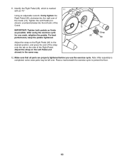
... pedals tightened. Place a mat beneath the exercise cycle to the desired position, and press the end of the strap onto the tab on the side of the Right Pedal. Tighten the Left Pedal (not shown) counterclockwise into the right arm of the Crank. Adjust the strap on the Left Pedal (not shown) in the same way. 13 26 Strap Tab 12. Using an adjustable wrench, firmly tighten...
... pedals tightened. Place a mat beneath the exercise cycle to the desired position, and press the end of the strap onto the tab on the side of the Right Pedal. Tighten the Left Pedal (not shown) counterclockwise into the right arm of the Crank. Adjust the strap on the Left Pedal (not shown) in the same way. 13 26 Strap Tab 12. Using an adjustable wrench, firmly tighten...

English Manual
Page 11
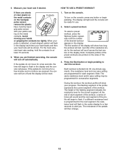
... USE THE EXERCISE CYCLE HOW TO ADJUST THE HEIGHT OF THE SEAT HOW TO ADJUST THE PEDAL STRAPS For effective exer- Next, pull the knob, slide the seat post upward or downward to the desired position, and then press the ends of the pedal straps onto the tabs. Then, tighten the knob. Seat Seat Knob 11 To adjust the pedal straps, first pull the ends of the seat, first loosen the seat knob...
... USE THE EXERCISE CYCLE HOW TO ADJUST THE HEIGHT OF THE SEAT HOW TO ADJUST THE PEDAL STRAPS For effective exer- Next, pull the knob, slide the seat post upward or downward to the desired position, and then press the ends of the pedal straps onto the tabs. Then, tighten the knob. Seat Seat Knob 11 To adjust the pedal straps, first pull the ends of the seat, first loosen the seat knob...
English Manual
Page 12
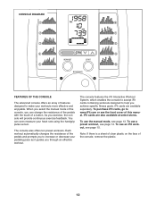
... achieve specific fitness goals. The console features the iFit Interactive Workout System, which enables the console to accept iFit cards containing workouts designed to help you exercise, the console will provide continuous exercise feedback. Note: If there is a sheet of clear plastic on the face of a button. When you select the manual mode of the console, you can even measure your heart rate using the handgrip pulse sensor. To purchase iFit cards, go...
... achieve specific fitness goals. The console features the iFit Interactive Workout System, which enables the console to accept iFit cards containing workouts designed to help you exercise, the console will provide continuous exercise feedback. Note: If there is a sheet of clear plastic on the face of a button. When you select the manual mode of the console, you can even measure your heart rate using the handgrip pulse sensor. To purchase iFit cards, go...
English Manual
Page 13
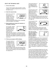
... the exercise cycle has been used will show speed and distance in the first section of hours the exercise cycle has been used , press and hold down the Workout button for use the handgrip pulse sensor (see step 5 on the console. Follow your progress with the display. Turn on page 14). To return to select the desired unit of the pedals. Select the manual mode. Each time you use . 2. Note...
... the exercise cycle has been used will show speed and distance in the first section of hours the exercise cycle has been used , press and hold down the Workout button for use the handgrip pulse sensor (see step 5 on the console. Follow your progress with the display. Turn on page 14). To return to select the desired unit of the pedals. Select the manual mode. Each time you use . 2. Note...
English Manual
Page 14
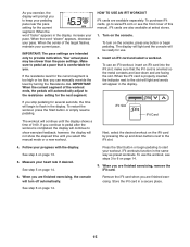
... pace setting are sheets of the resistance levels for at least 15 seconds. 6. For the most accu- The display will light and the console will begin pedaling. A profile of clear plastic on Contacts the metal contacts on the handgrip pulse sensor, remove the plastic. Press the Start button or begin to flash. At the end of each segment of the workout, a series of...
... pace setting are sheets of the resistance levels for at least 15 seconds. 6. For the most accu- The display will light and the console will begin pedaling. A profile of clear plastic on Contacts the metal contacts on the handgrip pulse sensor, remove the plastic. Press the Start button or begin to flash. At the end of each segment of the workout, a series of...
English Manual
Page 15
... finished exercising, remove the iFit card. 6. Turn on page 14. To turn off automatically. To use the workout, see the front cover of 0:00. IMPORTANT: When the current segment of the target flashes, maintain your pace. If you stop pedaling for several seconds, the time will begin pedaling. Press the Start button or begin pedaling to flash in the display, increase your current pace. See step 5 on the console...
... finished exercising, remove the iFit card. 6. Turn on page 14. To turn off automatically. To use the workout, see the front cover of 0:00. IMPORTANT: When the current segment of the target flashes, maintain your pace. If you stop pedaling for several seconds, the time will begin pedaling. Press the Start button or begin pedaling to flash in the display, increase your current pace. See step 5 on the console...
English Manual
Page 16
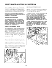
... pulse sensor, see assembly step 8 on page 14. Using an adjustable wrench, turn the right pedal clockwise and remove it . HOW TO ADJUST THE REED SWITCH To adjust the drive belt, you must first remove the left pedal and the left pedal. 45 69 16 21 61 13 16 To clean the exercise cycle, use a damp cloth and a small amount of screw you remove from each hole. CONSOLE TROUBLESHOOTING If the console display becomes dim, the batteries...
... pulse sensor, see assembly step 8 on page 14. Using an adjustable wrench, turn the right pedal clockwise and remove it . HOW TO ADJUST THE REED SWITCH To adjust the drive belt, you must first remove the left pedal and the left pedal. 45 69 16 21 61 13 16 To clean the exercise cycle, use a damp cloth and a small amount of screw you remove from each hole. CONSOLE TROUBLESHOOTING If the console display becomes dim, the batteries...
English Manual
Page 17
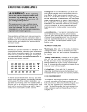
... determining heart rate trends in general. For maximum fat burning, exercise with pre-existing health problems. The pulse sensor is near the middle number in your training zone. Stretching increases the flexibility of your muscles and helps to the nearest ten years). Remember, the key to success is to make exercise a regular and enjoyable part of your exercise until your heart rate is the key to...
... determining heart rate trends in general. For maximum fat burning, exercise with pre-existing health problems. The pulse sensor is near the middle number in your training zone. Stretching increases the flexibility of your muscles and helps to the nearest ten years). Remember, the key to success is to make exercise a regular and enjoyable part of your exercise until your heart rate is the key to...
English Manual
Page 18
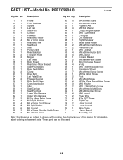
... 1 Short C-magnet Spacer 19 1 Resistance Motor Bracket 58 4 V-clip 20 1 Seat Post Bushing 59 1 M10 x 80mm Shoulder Bolt 21 1 Reed Switch/Wire 60 1 Resistance Wheel 22 2 Clamp 61 7 M4 x 16mm Flange Screw 23 1 Drive Belt 62 1 M3.5 x 12mm Screw 24 1 Left Pedal/Strap 63 2 Foot 25 2 Flywheel Bearing 64 1 M4 x 5mm Screw 26 1 Right Pedal/Strap 65 4 M3.8 x 20mm Round Head Screw 27 1 Crank Bearing Set 66 3 M10 Washer 28...
... 1 Short C-magnet Spacer 19 1 Resistance Motor Bracket 58 4 V-clip 20 1 Seat Post Bushing 59 1 M10 x 80mm Shoulder Bolt 21 1 Reed Switch/Wire 60 1 Resistance Wheel 22 2 Clamp 61 7 M4 x 16mm Flange Screw 23 1 Drive Belt 62 1 M3.5 x 12mm Screw 24 1 Left Pedal/Strap 63 2 Foot 25 2 Flywheel Bearing 64 1 M4 x 5mm Screw 26 1 Right Pedal/Strap 65 4 M3.8 x 20mm Round Head Screw 27 1 Crank Bearing Set 66 3 M10 Washer 28...
English Manual
Page 19
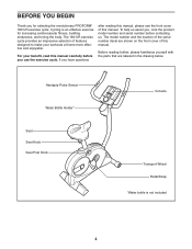
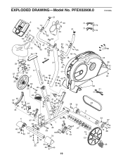
PFEX02908.0 R1108A 51 6 74 75 50 40 51 49 50 55 12 56 65 54 47 40 43 43 53 32 74 54 75 65 40 43 43 48 29 36 37 37 66 25 36 11 37 5 36 7 66 25 20 3 53 40 35 36 17 36 40 36 36 35 46 57 44 42 24 62 10 60 8 52 28 66 4 37 69 40 63 40 14 34 64 30 21 61 22 61 38 15 22 68 1 76 61 45 59 70 73 9 27 19 61 34 33 40 63 40 71 72 71 72 58 18 39 39 41 40 40 31 23 2 16 13 34 67 34 15 38 26 19 EXPLODED DRAWING-Model No.
PFEX02908.0 R1108A 51 6 74 75 50 40 51 49 50 55 12 56 65 54 47 40 43 43 53 32 74 54 75 65 40 43 43 48 29 36 37 37 66 25 36 11 37 5 36 7 66 25 20 3 53 40 35 36 17 36 40 36 36 35 46 57 44 42 24 62 10 60 8 52 28 66 4 37 69 40 63 40 14 34 64 30 21 61 22 61 38 15 22 68 1 76 61 45 59 70 73 9 27 19 61 34 33 40 63 40 71 72 71 72 58 18 39 39 41 40 40 31 23 2 16 13 34 67 34 15 38 26 19 EXPLODED DRAWING-Model No.
English Manual
Page 20
... revenues or profits, loss of enjoyment or use, or costs of removal or installation; This warranty gives you . ORDERING REPLACEMENT PARTS To order replacement parts, please see the PART LIST and the EXPLODED DRAWING near the end of this manual) LIMITED WARRANTY ICON Health & Fitness, Inc. (ICON) warrants this product to be free from the date of purchase. products used as store display models. or other consequential damages of merchantability or...
... revenues or profits, loss of enjoyment or use, or costs of removal or installation; This warranty gives you . ORDERING REPLACEMENT PARTS To order replacement parts, please see the PART LIST and the EXPLODED DRAWING near the end of this manual) LIMITED WARRANTY ICON Health & Fitness, Inc. (ICON) warrants this product to be free from the date of purchase. products used as store display models. or other consequential damages of merchantability or...

