

User Manual
Page 1
Write the serial number in this equipment. USER'S MANUAL Serial Number Decal (under frame) QUESTIONS? www.proform.com Model No. PFEL55911.0 Serial No. MT Sat. 8 a.m.-4 p.m. If you have questions, or if parts are damaged or missing, DO NOT CONTACT THE STORE; Keep this manual for reference. IMPORTANT: Please register this product (see the...
Write the serial number in this equipment. USER'S MANUAL Serial Number Decal (under frame) QUESTIONS? www.proform.com Model No. PFEL55911.0 Serial No. MT Sat. 8 a.m.-4 p.m. If you have questions, or if parts are damaged or missing, DO NOT CONTACT THE STORE; Keep this manual for reference. IMPORTANT: Please register this product (see the...

User Manual
Page 2
...PROFORM is missing or illegible, see the front cover of this manual and request a free replacement decal. If a decal is a registered trademark of the warning decal(s). Apply the decal in the location shown. TABLE OF CONTENTS WARNING DECAL PLACEMENT 2 IMPORTANT PRECAUTIONS 3 BEFORE YOU BEGIN 4 PART IDENTIFICATION CHART 5 ASSEMBLY 6 HOW TO USE THE ELLIPTICAL... 15 FCC INFORMATION 23 MAINTENANCE AND TROUBLESHOOTING 24 EXERCISE GUIDELINES 26 PART LIST 27 EXPLODED DRAWING 29 ORDERING REPLACEMENT PARTS Back Cover...
...PROFORM is missing or illegible, see the front cover of this manual and request a free replacement decal. If a decal is a registered trademark of the warning decal(s). Apply the decal in the location shown. TABLE OF CONTENTS WARNING DECAL PLACEMENT 2 IMPORTANT PRECAUTIONS 3 BEFORE YOU BEGIN 4 PART IDENTIFICATION CHART 5 ASSEMBLY 6 HOW TO USE THE ELLIPTICAL... 15 FCC INFORMATION 23 MAINTENANCE AND TROUBLESHOOTING 24 EXERCISE GUIDELINES 26 PART LIST 27 EXPLODED DRAWING 29 ORDERING REPLACEMENT PARTS Back Cover...

User Manual
Page 3
...(125 kg). 10. Use the elliptical only as an exercise aid in determining heart rate trends in serious injury or death. The elliptical should not be used by or through the use the elliptical in the front and rear of the elliptical and 2 ft. (0.6 m) on your elliptical before using your .... 1. Hold the handlebars or the upper body arms when mounting, dismounting, or using the elliptical; To protect the floor or carpet from moisture and dust. Inspect and properly tighten all parts regularly. If you feel faint or if you experience pain while exercising, stop immediately and cool...
...(125 kg). 10. Use the elliptical only as an exercise aid in determining heart rate trends in serious injury or death. The elliptical should not be used by or through the use the elliptical in the front and rear of the elliptical and 2 ft. (0.6 m) on your elliptical before using your .... 1. Hold the handlebars or the upper body arms when mounting, dismounting, or using the elliptical; To protect the floor or carpet from moisture and dust. Inspect and properly tighten all parts regularly. If you feel faint or if you experience pain while exercising, stop immediately and cool...

User Manual
Page 4
... yourself with the parts that are labeled in . (66 cm) Handlebar Accessory Tray Console Heart Rate Monitor Upper Body Arm Pedal Disc Handle Leveling Foot Wheel Adjustment Knob Storage Latch 4 manual. To help us . The 10.0 CE elliptical provides an impressive selection of this manual. If you for selecting the revolutionary PROFORM® 10.0 CE elliptical. BEFORE YOU...
... yourself with the parts that are labeled in . (66 cm) Handlebar Accessory Tray Console Heart Rate Monitor Upper Body Arm Pedal Disc Handle Leveling Foot Wheel Adjustment Knob Storage Latch 4 manual. To help us . The 10.0 CE elliptical provides an impressive selection of this manual. If you for selecting the revolutionary PROFORM® 10.0 CE elliptical. BEFORE YOU...

User Manual
Page 5
Extra parts may be included. M8 Split Washer (131)-6 M8 x 23mm x 1.5mm Washer (126)-10 M10 Split Washer (128)-4 Wave Washer (118)-2 M8 Locknut (105)-6 M4 x 16mm Screw (93)-16 M4 x 25mm Screw (132)-2 M6 x 12mm Screw (111)-2 M8 x 16mm ...)-6 M10 x 120mm Screw (100)-4 5 The number in the hardware kit, check to identify the small parts needed for assembly. PART IDENTIFICATION CHART Use the drawings below each drawing is the key number of the part, from the PART LIST near the end of this manual. The number following the key number is not in...
Extra parts may be included. M8 Split Washer (131)-6 M8 x 23mm x 1.5mm Washer (126)-10 M10 Split Washer (128)-4 Wave Washer (118)-2 M8 Locknut (105)-6 M4 x 16mm Screw (93)-16 M4 x 25mm Screw (132)-2 M6 x 12mm Screw (111)-2 M8 x 16mm ...)-6 M10 x 120mm Screw (100)-4 5 The number in the hardware kit, check to identify the small parts needed for assembly. PART IDENTIFICATION CHART Use the drawings below each drawing is the key number of the part, from the PART LIST near the end of this manual. The number following the key number is not in...

User Manual
Page 6
... tools: one Phillips screwdriver one rubber mallet Assembly may be easier if you complete all parts in the folded position. While a second person lifts the Folding Frame (2), attach the Rear Stabilizer (4) to the Folding Frame with the elliptical in a cleared area and remove the packing materials. Identify and orient the Rear Stabilizer...
... tools: one Phillips screwdriver one rubber mallet Assembly may be easier if you complete all parts in the folded position. While a second person lifts the Folding Frame (2), attach the Rear Stabilizer (4) to the Folding Frame with the elliptical in a cleared area and remove the packing materials. Identify and orient the Rear Stabilizer...

User Manual
Page 10
...turns into the Rear Upright Cover (24). 25 5 24 11. Orient a Pedal Arm (12) as shown. Then, tighten both parts. Apply a small amount of the Short Pedal Arm Axle (115). Tighten another M8 x 16mm Screw (102) and an M8 ... Axle (115) and to the Upright (5) with four M4 x 16mm Screws (93). 9 93 5 24 10. Attach the Front Upright Cover (25) around the Upright (5) by pressing the tabs on the other side of... a second person holds the front end of the elliptical. 11 102 126 Grease 115 12 51 126 102 10 Repeat this step on the Front 10 Upright Cover into the Short Pedal Arm Axle (115...
...turns into the Rear Upright Cover (24). 25 5 24 11. Orient a Pedal Arm (12) as shown. Then, tighten both parts. Apply a small amount of the Short Pedal Arm Axle (115). Tighten another M8 x 16mm Screw (102) and an M8 ... Axle (115) and to the Upright (5) with four M4 x 16mm Screws (93). 9 93 5 24 10. Attach the Front Upright Cover (25) around the Upright (5) by pressing the tabs on the other side of... a second person holds the front end of the elliptical. 11 102 126 Grease 115 12 51 126 102 10 Repeat this step on the Front 10 Upright Cover into the Short Pedal Arm Axle (115...

User Manual
Page 11
While a second person holds the front end of the right Pedal Arm (12) inside the bracket on the other side of the elliptical. 14. Next, tighten an M8 x 16mm Screw (102) and an M8 x 23mm x 1.5mm Washer (126) a few turns into one end of grease to a Long Pedal ... the same time. Attach the Left Pedal (not shown) to the Right Upper Body Leg (6) with three M8 x 50mm Button Screws (123). Then, tighten both parts. Press the Right Inner and Outer Leg Covers (27, 28) together around the Right Upper Body Leg (6). Apply a small amount of the Long Pedal Arm...
While a second person holds the front end of the right Pedal Arm (12) inside the bracket on the other side of the elliptical. 14. Next, tighten an M8 x 16mm Screw (102) and an M8 x 23mm x 1.5mm Washer (126) a few turns into one end of grease to a Long Pedal ... the same time. Attach the Left Pedal (not shown) to the Right Upper Body Leg (6) with three M8 x 50mm Button Screws (123). Then, tighten both parts. Press the Right Inner and Outer Leg Covers (27, 28) together around the Right Upper Body Leg (6). Apply a small amount of the Long Pedal Arm...

User Manual
Page 14
... Wire (60) and to the Console (33) with four M4 x 16mm Screws (93). 20 33 Avoid pinching the wires 135 10 60 93 21. Attach the Console (33) to the Handlebar (10) with two M4 x 16mm Screws (93). 21 33 93 11 22. Note: Some hardware may be left over after assembly... TO PLUG IN THE POWER ADAPTER on page 15. 23. Attach the Console Cover (11) to the Pulse Wire (135). 20. Make sure that all parts of the elliptical. 22 136 To plug the Power Adapter (136) into the Handlebar...
... Wire (60) and to the Console (33) with four M4 x 16mm Screws (93). 20 33 Avoid pinching the wires 135 10 60 93 21. Attach the Console (33) to the Handlebar (10) with two M4 x 16mm Screws (93). 21 33 93 11 22. Note: Some hardware may be left over after assembly... TO PLUG IN THE POWER ADAPTER on page 15. 23. Attach the Console Cover (11) to the Pulse Wire (135). 20. Make sure that all parts of the elliptical. 22 136 To plug the Power Adapter (136) into the Handlebar...

User Manual
Page 23
... that to which can radiate radio frequency energy and, if not installed and used in accordance with the limits for a Class B digital device, pursuant to part 15 of the following measures: • Reorient or relocate the receiving antenna. • Increase the separation between the equipment and the receiver. • Connect the...
... that to which can radiate radio frequency energy and, if not installed and used in accordance with the limits for a Class B digital device, pursuant to part 15 of the following measures: • Reorient or relocate the receiving antenna. • Increase the separation between the equipment and the receiver. • Connect the...

User Manual
Page 24
...and a small amount of the elliptical regularly. Next, rotate the Large Pulley (74) until the console displays correct feedback. Rotate the Large Pulley (74) for a moment. When the reed switch is aligned with the Reed Switch (69). Replace any worn parts immediately. CONSOLE TROUBLESHOOTING 93 69...- Repeat these actions until a Magnet (75) is correctly adjusted, reattach the top shield. 24 MAINTENANCE AND TROUBLESHOOTING Inspect and tighten all parts of mild soap. Loosen, but do not remove, the M4 x 16mm Screw (93). Slide the Reed Switch slightly toward or away from...
...and a small amount of the elliptical regularly. Next, rotate the Large Pulley (74) until the console displays correct feedback. Rotate the Large Pulley (74) for a moment. When the reed switch is aligned with the Reed Switch (69). Replace any worn parts immediately. CONSOLE TROUBLESHOOTING 93 69...- Repeat these actions until a Magnet (75) is correctly adjusted, reattach the top shield. 24 MAINTENANCE AND TROUBLESHOOTING Inspect and tighten all parts of mild soap. Loosen, but do not remove, the M4 x 16mm Screw (93). Slide the Reed Switch slightly toward or away from...

User Manual
Page 26
...of stretching and light exercise. After a few minutes of exercise, your body begin to 10 minutes of heart rate readings. Cooling Down-Finish with 5 to use your heart rate as a guide to 10 minutes of your training zone. Remember, proper nutrition and adequate rest are rounded off ...to make exercise a regular and enjoyable part of stretching. The lowest number is the heart rate for fat burning, the middle...
...of stretching and light exercise. After a few minutes of exercise, your body begin to 10 minutes of heart rate readings. Cooling Down-Finish with 5 to use your heart rate as a guide to 10 minutes of your training zone. Remember, proper nutrition and adequate rest are rounded off ...to make exercise a regular and enjoyable part of stretching. The lowest number is the heart rate for fat burning, the middle...

User Manual
Page 27
PFEL55911.0 R0911A Key No. Qty. 1 1 2 1 3 1 4 1 5 1 6 1 7 1 8 1 9 1 10 1 11 1 12 2 13 1 14 1 15 1 16 2 17 2 18 1 19 1 20 1 21 1 22 1 23 1 24 1 25 1 26 1 27 1 28 1 29 1 30 1 31 1 32 1 33 1 34 2 35 2... Latch Bracket Adjustment Bracket Adjustment Pin Adjustment Knob Knob Cap Pivot Arm Bushing Upright Axle Left Inner Leg Cover Left Outer Leg Cover Model No. PART LIST Key No. Qty. 51 1 52 1 53 2 54 2 55 1 56 1 57 6 58 1 59 1 60 1 61 1 62 4 63 1 64 2 65 1 66 1 67 1 68 1 69 1 70 1 71...
PFEL55911.0 R0911A Key No. Qty. 1 1 2 1 3 1 4 1 5 1 6 1 7 1 8 1 9 1 10 1 11 1 12 2 13 1 14 1 15 1 16 2 17 2 18 1 19 1 20 1 21 1 22 1 23 1 24 1 25 1 26 1 27 1 28 1 29 1 30 1 31 1 32 1 33 1 34 2 35 2... Latch Bracket Adjustment Bracket Adjustment Pin Adjustment Knob Knob Cap Pivot Arm Bushing Upright Axle Left Inner Leg Cover Left Outer Leg Cover Model No. PART LIST Key No. Qty. 51 1 52 1 53 2 54 2 55 1 56 1 57 6 58 1 59 1 60 1 61 1 62 4 63 1 64 2 65 1 66 1 67 1 68 1 69 1 70 1 71...
User Manual
Page 28
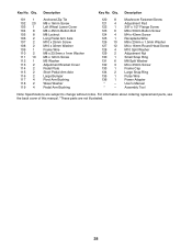
... Bracket Cover Pedal Plate Short Pedal Arm Axle Large Bumper Pivot Arm Bushing Wave Washer Pedal Arm Bushing 120 8 121 4 122 1 123 6 124 4 125 1 126 10 127 12 128 4 129 2 130 1 131 6 132 3 133 1 134 2 135 1 136 1 * - * - Mushroom Fastener/Screw Adjustment Pad 3/8" x 1/2" Flange Screw M8 x 50mm Button Screw...Pulse Wire Power Adapter Userʼs Manual Assembly Tool Note: Specifications are not illustrated. 28 Qty. For information about ordering replacement parts, see the back cover of this manual. *These parts are subject to change without notice. Qty. Key No.
... Bracket Cover Pedal Plate Short Pedal Arm Axle Large Bumper Pivot Arm Bushing Wave Washer Pedal Arm Bushing 120 8 121 4 122 1 123 6 124 4 125 1 126 10 127 12 128 4 129 2 130 1 131 6 132 3 133 1 134 2 135 1 136 1 * - * - Mushroom Fastener/Screw Adjustment Pad 3/8" x 1/2" Flange Screw M8 x 50mm Button Screw...Pulse Wire Power Adapter Userʼs Manual Assembly Tool Note: Specifications are not illustrated. 28 Qty. For information about ordering replacement parts, see the back cover of this manual. *These parts are subject to change without notice. Qty. Key No.

User Manual
Page 32
...this product to state. Some states do not allow limitations on how long an implied warranty lasts. This warranty provides specific legal rights; Parts and labor are warranted for a particular purpose are shipped while the product is not responsible or liable for indirect, special, or consequential... to the product. damages with the use and service conditions. ICON Health & Fitness, Inc., 1500 S. 1000 W., Logan, UT 84321-9813 Part No. 319553 R0911A Printed in -home service, the customer will be voided if the product is used for service needed under normal use or ...
...this product to state. Some states do not allow limitations on how long an implied warranty lasts. This warranty provides specific legal rights; Parts and labor are warranted for a particular purpose are shipped while the product is not responsible or liable for indirect, special, or consequential... to the product. damages with the use and service conditions. ICON Health & Fitness, Inc., 1500 S. 1000 W., Logan, UT 84321-9813 Part No. 319553 R0911A Printed in -home service, the customer will be voided if the product is used for service needed under normal use or ...


