
User Manual
Page 4
... outlets and extensions. 2 WARNING This symbol is intended to alert the user to install a grounding outlet. ▪ Always operate this equipment from the type of power source indicated on the 3-prong plug is intended to alert the user to the presence of fire or electric shock, do not expose this...
... outlets and extensions. 2 WARNING This symbol is intended to alert the user to install a grounding outlet. ▪ Always operate this equipment from the type of power source indicated on the 3-prong plug is intended to alert the user to the presence of fire or electric shock, do not expose this...

User Manual
Page 5
... direct sunlight, as the equipment may expose you to rain or moisture, does not operate normally, or has been dropped. ▪ Always remove the power cord from the outlet before cleaning the equipment. ▪ Never use liquid or aerosol cleaners on the equipment. The equipment may cause poor ventilation. &#...place or drop any of time. ▪ Refer all servicing to liquid, rain, or moisture. Do not handle the AC power cord with a wet hand. ▪ Do not touch the power cord and antenna cable during lightning storms or when unused for a long period of time. ▪ Do not place, use...
... direct sunlight, as the equipment may expose you to rain or moisture, does not operate normally, or has been dropped. ▪ Always remove the power cord from the outlet before cleaning the equipment. ▪ Never use liquid or aerosol cleaners on the equipment. The equipment may cause poor ventilation. &#...place or drop any of time. ▪ Refer all servicing to liquid, rain, or moisture. Do not handle the AC power cord with a wet hand. ▪ Do not touch the power cord and antenna cable during lightning storms or when unused for a long period of time. ▪ Do not place, use...

User Manual
Page 6
...wire Ground clamps Electric service equipment Antenna discharge unit (NEC section 810-20) Grounding conductors (NEC section 810-20) Ground clamps Power service grounding (NEC Art250 part H) NEC : National Electrical code EXAMPLE OF OUTDOOR ANTENNA GROUNDING 4 Section 810 of National Electrical Code...in wire to an antenna discharge unit, size of grounding conductors, location of antenna discharge unit, connection to prevent contact with power lines. Warnings and Precautions Outdoor Antenna Safety Instructions If an outdoor antenna is connected, follow the precautions below: ▪ An ...
...wire Ground clamps Electric service equipment Antenna discharge unit (NEC section 810-20) Grounding conductors (NEC section 810-20) Ground clamps Power service grounding (NEC Art250 part H) NEC : National Electrical code EXAMPLE OF OUTDOOR ANTENNA GROUNDING 4 Section 810 of National Electrical Code...in wire to an antenna discharge unit, size of grounding conductors, location of antenna discharge unit, connection to prevent contact with power lines. Warnings and Precautions Outdoor Antenna Safety Instructions If an outdoor antenna is connected, follow the precautions below: ▪ An ...
User Manual
Page 9
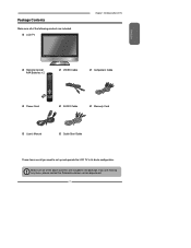
... the LCD TV ENGLISH Remote Control/ AAA Batteries x 2 S.MODE MTS P. MODE CAPTION SLEEP P.SIZE MUTE VOL. GUIDE EXIT INFO MENU LIST FREEZE FAV.CH TIMER Power Cord VIDEO Cable AUDIO Cable Component Cable Warranty Card User's Manual Quick Start Guide These items are all you are included in its basic con.... Package Contents Make sure all of the following contents are included. Make sure all of the above contents are missing any items, please contact the Polaroid customer service department. 7
... the LCD TV ENGLISH Remote Control/ AAA Batteries x 2 S.MODE MTS P. MODE CAPTION SLEEP P.SIZE MUTE VOL. GUIDE EXIT INFO MENU LIST FREEZE FAV.CH TIMER Power Cord VIDEO Cable AUDIO Cable Component Cable Warranty Card User's Manual Quick Start Guide These items are all you are included in its basic con.... Package Contents Make sure all of the following contents are included. Make sure all of the above contents are missing any items, please contact the Polaroid customer service department. 7

User Manual
Page 11
... Insert two AAA size batteries. Connect other an external AV device (refer to the LCD TV's ANT. Connect the AC power cord at the back of the TV and connect the power cord to match the (+) and ( - ) ends of the remote control. Make sure to wall outlet. Slide the cover back into...
... Insert two AAA size batteries. Connect other an external AV device (refer to the LCD TV's ANT. Connect the AC power cord at the back of the TV and connect the power cord to match the (+) and ( - ) ends of the remote control. Make sure to wall outlet. Slide the cover back into...

User Manual
Page 13
..., high-definition video and two-channel digital audio. VHF/UHF IN Connects RF input from VHF/UHF antenna or cable to the AC power cord. HDMI IN Y Pb Pr VIDEO IN S-VIDEO IN COAXIAL VHF/UHF IN PC/VGA IN PC AUDIO IN L AUDIO IN R L AUDIO IN R AC IN...
..., high-definition video and two-channel digital audio. VHF/UHF IN Connects RF input from VHF/UHF antenna or cable to the AC power cord. HDMI IN Y Pb Pr VIDEO IN S-VIDEO IN COAXIAL VHF/UHF IN PC/VGA IN PC AUDIO IN L AUDIO IN R L AUDIO IN R AC IN...

User Manual
Page 16
... Cable or an Antenna Antenna Connection The antenna requirements for a black & white TV reception. The following is a brief explanation of the type of any AC power cords to wall outlets until all other connections are more important than those for good color TV reception are completed.
... Cable or an Antenna Antenna Connection The antenna requirements for a black & white TV reception. The following is a brief explanation of the type of any AC power cords to wall outlets until all other connections are more important than those for good color TV reception are completed.

User Manual
Page 19
... when the LCD TV will not be used for a long period of the TV and connect the power cord to the LCD TV's TV CABLE terminal. To completely disconnect the main voltage, please remove the power plug from the main voltage. ENGLISH Chapter 2 Installing the LCD TV Use a supplied antenna cable to... connect the TV signal to wall outlet. The POWER button on the LCD TV. VHF/UHF IN Connect the AC power cord at the back of time. Press the button on the remote to turn on the front panel is only...
... when the LCD TV will not be used for a long period of the TV and connect the power cord to the LCD TV's TV CABLE terminal. To completely disconnect the main voltage, please remove the power plug from the main voltage. ENGLISH Chapter 2 Installing the LCD TV Use a supplied antenna cable to... connect the TV signal to wall outlet. The POWER button on the LCD TV. VHF/UHF IN Connect the AC power cord at the back of time. Press the button on the remote to turn on the front panel is only...

User Manual
Page 21
To view the A/V device's with Composite Connector Rear of the LCD TV or other connected equipment. Not all AC power sources, before turning on the power switch of TV HDMI IN Y Pb Pr VIDEO IN S-VIDEO IN COAXIAL VHF/UHF IN PC/VGA IN PC AUDIO IN L AUDIO IN R L AUDIO IN R ...
To view the A/V device's with Composite Connector Rear of the LCD TV or other connected equipment. Not all AC power sources, before turning on the power switch of TV HDMI IN Y Pb Pr VIDEO IN S-VIDEO IN COAXIAL VHF/UHF IN PC/VGA IN PC AUDIO IN L AUDIO IN R L AUDIO IN R ...

User Manual
Page 22
Connect all AC power sources, before turning on the remote repeatedly to the LCD TV's audio inputs. To view the A/V device's with S-Video Connector Rear of the LCD TV ... to the LCD TV's S-Video IN input jack. Chapter 2 Installing the LCD TV Connecting an A/V Device with component input, press the INPUT button on the power switch of TV HDMI IN Y Pb Pr VIDEO IN S-VIDEO IN COAXIAL VHF/UHF IN PC/VGA IN PC AUDIO IN L AUDIO IN R GAME CONSOLE...
Connect all AC power sources, before turning on the remote repeatedly to the LCD TV's audio inputs. To view the A/V device's with S-Video Connector Rear of the LCD TV ... to the LCD TV's S-Video IN input jack. Chapter 2 Installing the LCD TV Connecting an A/V Device with component input, press the INPUT button on the power switch of TV HDMI IN Y Pb Pr VIDEO IN S-VIDEO IN COAXIAL VHF/UHF IN PC/VGA IN PC AUDIO IN L AUDIO IN R GAME CONSOLE...

User Manual
Page 23
... Pr Cb Cr AUDIO Cable COMPONENT Cable Pr/Cr Pb/Pb COMPONENT OUT GAME CONSOLE R L Pb Pr D V D PLA YER Y Not all AC power sources, before turning on the power switch of component video, see your A/V device's user guide. 21 The component video jacks on your A/V device user guide for compatibility. Use a component...
... Pr Cb Cr AUDIO Cable COMPONENT Cable Pr/Cr Pb/Pb COMPONENT OUT GAME CONSOLE R L Pb Pr D V D PLA YER Y Not all AC power sources, before turning on the power switch of component video, see your A/V device's user guide. 21 The component video jacks on your A/V device user guide for compatibility. Use a component...

User Manual
Page 24
... TV. The HDMI connector provides both video and audio signals, it's not necessary to the LCD TV's HDMI IN jacks. Connect all AC power sources, before turning on the power switch of TV HDMI IN Y Pb Pr VIDEO IN S-VIDEO IN COAXIAL VHF/UHF IN PC/VGA IN PC AUDIO IN L AUDIO...
... TV. The HDMI connector provides both video and audio signals, it's not necessary to the LCD TV's HDMI IN jacks. Connect all AC power sources, before turning on the power switch of TV HDMI IN Y Pb Pr VIDEO IN S-VIDEO IN COAXIAL VHF/UHF IN PC/VGA IN PC AUDIO IN L AUDIO...

User Manual
Page 25
Use an audio cable to connect the AV equipment's audio output jacks to turn on the LCD TV. Press the Input button on the power switch of TV HDMI IN Y Pb Pr VIDEO IN S-VIDEO IN COAXIAL VHF/UHF IN PC/VGA IN PC AUDIO IN L AUDIO IN R L AUDIO IN R ... AV EQUIPMENT Use a HDMI-to-DVI cable to connect the AV equipment's DVI output jack to the LCD TV's HDMI IN jacks. Connect all AC power sources, before turning on the remote to -DVI cable or an HDMI adapter(not supplied) and an audio cable. 23 Connecting an AV Equipment with...
Use an audio cable to connect the AV equipment's audio output jacks to turn on the LCD TV. Press the Input button on the power switch of TV HDMI IN Y Pb Pr VIDEO IN S-VIDEO IN COAXIAL VHF/UHF IN PC/VGA IN PC AUDIO IN L AUDIO IN R L AUDIO IN R ... AV EQUIPMENT Use a HDMI-to-DVI cable to connect the AV equipment's DVI output jack to the LCD TV's HDMI IN jacks. Connect all AC power sources, before turning on the remote to -DVI cable or an HDMI adapter(not supplied) and an audio cable. 23 Connecting an AV Equipment with...

User Manual
Page 26
Press the button on the remote to turn on the remote to select COMPUTER. 24 Press the INPUT button on the LCD TV. Connect all AC power sources, before turning on the power switch of TV HDMI IN Y Pb Pr VIDEO IN S-VIDEO IN COAXIAL VHF/UHF IN PC/VGA IN PC AUDIO IN L AUDIO IN R L AUDIO IN R AUDIO Cable VGA Cable PC Use a D-SUB cable to connect the PC's D-SUB output jack to LCD TV's. Use an audio cable to connect the PC's audio output jacks to the LCD TV's VGA input jack. Chapter 3 Using the LCD TV Connecting a PC Rear of the LCD TV or other connected equipment.
Press the button on the remote to turn on the remote to select COMPUTER. 24 Press the INPUT button on the LCD TV. Connect all AC power sources, before turning on the power switch of TV HDMI IN Y Pb Pr VIDEO IN S-VIDEO IN COAXIAL VHF/UHF IN PC/VGA IN PC AUDIO IN L AUDIO IN R L AUDIO IN R AUDIO Cable VGA Cable PC Use a D-SUB cable to connect the PC's D-SUB output jack to LCD TV's. Use an audio cable to connect the PC's audio output jacks to the LCD TV's VGA input jack. Chapter 3 Using the LCD TV Connecting a PC Rear of the LCD TV or other connected equipment.

User Manual
Page 27
...Home Theater/ Stereo System to use the TV audio output to make this connection. Although not recommended, if you prefer to use with your new Polaroid TV, we recommend that you would like to your TV's audio output for this connection to your Home Stereo System, please follow the instructions ... cable to connect the audio receiver's audio LINE IN jacks to use your DVD player, Cable/Satellite box or other connected equipment. Connect all AC power sources, before turning on the LCD TV. 25 NOTE: If you have a Home Theater/Stereo System that you do NOT use a Home Theater/Stereo...
...Home Theater/ Stereo System to use the TV audio output to make this connection. Although not recommended, if you prefer to use with your new Polaroid TV, we recommend that you would like to your TV's audio output for this connection to your Home Stereo System, please follow the instructions ... cable to connect the audio receiver's audio LINE IN jacks to use your DVD player, Cable/Satellite box or other connected equipment. Connect all AC power sources, before turning on the LCD TV. 25 NOTE: If you have a Home Theater/Stereo System that you do NOT use a Home Theater/Stereo...
User Manual
Page 46
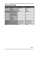
Specifications SPECIFICATIONS LCD Panel Panel Size 15.4" TFT LCD 19" TFT LCD Brightness 200 300 Contrast Ratio 400:1 850:1 Max. Resolution 1280x800 1400x900 Input Connector VIDEO/AUDIO IN(L/R) 1 1 S-VIDEO/AUDIO IN(L/R) 1 1 YPbPr/AUDIO IN(L/R) 1 1 PC(VGA IN)/PC AUDIO IN 1 1 HDMI 1 1 COAXIAL OUT 1 1 HEADPHONE 1 1 VHF/UHF IN 1 1 Power Source AC100~240V, 50/60HZ, 1.2A AC100~240V, 50/60HZ, 1.2A Power Consumption 50 W, standby < 5 W 65 W, standby < 5 W Dimension 15.2 w x 13.5 h x 5.2 d inch 18 w x 15.9 h x 5.2 d inch WEIGHT 31.97 LB 39.5 LB 20070205 44
Specifications SPECIFICATIONS LCD Panel Panel Size 15.4" TFT LCD 19" TFT LCD Brightness 200 300 Contrast Ratio 400:1 850:1 Max. Resolution 1280x800 1400x900 Input Connector VIDEO/AUDIO IN(L/R) 1 1 S-VIDEO/AUDIO IN(L/R) 1 1 YPbPr/AUDIO IN(L/R) 1 1 PC(VGA IN)/PC AUDIO IN 1 1 HDMI 1 1 COAXIAL OUT 1 1 HEADPHONE 1 1 VHF/UHF IN 1 1 Power Source AC100~240V, 50/60HZ, 1.2A AC100~240V, 50/60HZ, 1.2A Power Consumption 50 W, standby < 5 W 65 W, standby < 5 W Dimension 15.2 w x 13.5 h x 5.2 d inch 18 w x 15.9 h x 5.2 d inch WEIGHT 31.97 LB 39.5 LB 20070205 44


