Operating Instructions
Page 4
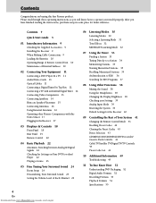
...Rear Panel 19 Remote Control 20 04 Basic Playback 22 Automatic Switching between Analog & Digital Signals 22 Checking the Settings on buying this fine Pioneer product. Contents 4 Quick Start Guide 5 01 Introductory Information 9 Checking the Supplied Accessories 9 Installing the Receiver 9 When Making Cable Connections ... Stations 34 Naming Memorized Stations 35 Recalling Memorized Stations 35 An Introduction to operate your Settings 39 Analog Input Mode 39 Resetting the System 39 Default Settings for the Receiver 40 09 Controlling the Rest of Your System 41 Changing the Remote Control ...
...Rear Panel 19 Remote Control 20 04 Basic Playback 22 Automatic Switching between Analog & Digital Signals 22 Checking the Settings on buying this fine Pioneer product. Contents 4 Quick Start Guide 5 01 Introductory Information 9 Checking the Supplied Accessories 9 Installing the Receiver 9 When Making Cable Connections ... Stations 34 Naming Memorized Stations 35 Recalling Memorized Stations 35 An Introduction to operate your Settings 39 Analog Input Mode 39 Resetting the System 39 Default Settings for the Receiver 40 09 Controlling the Rest of Your System 41 Changing the Remote Control ...
Operating Instructions
Page 39
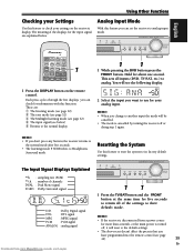
... (DVD, TV/SAT, etc.) to analog. Hold for your analog input. Resetting the System Use this feature to check your settings on the remote control. AUDIO/VIDEO MULTI-CHANNEL RECEIVER VSX-C300 VIRTUAL DTS MPEG PHONES SURR. MEMO: • If the receiver is disconnected ...from www.Manualslib.com manuals search engine English Using Other Functions Checking your Settings Use this feature to reset the system to its factory default ...
... (DVD, TV/SAT, etc.) to analog. Hold for your analog input. Resetting the System Use this feature to check your settings on the remote control. AUDIO/VIDEO MULTI-CHANNEL RECEIVER VSX-C300 VIRTUAL DTS MPEG PHONES SURR. MEMO: • If the receiver is disconnected ...from www.Manualslib.com manuals search engine English Using Other Functions Checking your Settings Use this feature to reset the system to its factory default ...
Operating Instructions
Page 40
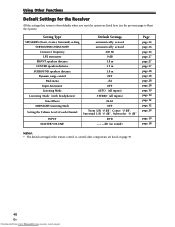
Using Other Functions Default Settings for the remote control to Reset the System). dB (no sound) Page page 26 page 26 page 26 page 27 page 27 page 27 page 28 page 28 page 28 page ... 32 page 29 page 19 page 18 MEMO: • The default settings for the Receiver All the settings that return to their defaults when you reset the system are listed here (see the previous page to control other components are listed on page 43. 40 En Downloaded from www.Manualslib.com...
Using Other Functions Default Settings for the remote control to Reset the System). dB (no sound) Page page 26 page 26 page 26 page 27 page 27 page 27 page 28 page 28 page 28 page ... 32 page 29 page 19 page 18 MEMO: • The default settings for the Receiver All the settings that return to their defaults when you reset the system are listed here (see the previous page to control other components are listed on page 43. 40 En Downloaded from www.Manualslib.com...
Operating Instructions
Page 43
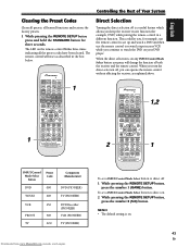
... Select button Preset Code DVD 000 TV/SAT 600 VCR 456 FRONT 400 TV 600 Component (Manufacturer) DVD (PIONEER) TV (PIONEER) DVD Recorder (PIONEER) VCR (PIONEER) TV (PIONEER) Downloaded from www.Manualslib.com manuals search engine To set a INPUT/Control Mode Select button to direct off ...is a useful feature which allows you press will reset as explained above. 2 RECEIVER DVD INPUT SELECT REMOTE ...
... Select button Preset Code DVD 000 TV/SAT 600 VCR 456 FRONT 400 TV 600 Component (Manufacturer) DVD (PIONEER) TV (PIONEER) DVD Recorder (PIONEER) VCR (PIONEER) TV (PIONEER) Downloaded from www.Manualslib.com manuals search engine To set a INPUT/Control Mode Select button to direct off ...is a useful feature which allows you press will reset as explained above. 2 RECEIVER DVD INPUT SELECT REMOTE ...
Service Manual
Page 55
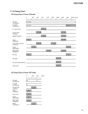
VSX-C300 7.1.5 Timing Chart Timing Chart of Power OFF Initial 0 200 400 (msec) AC relay (UCOM port) A. MUTE (UCOM port) FL, LED control Function SW (TC9164) Speaker detection "H" (ON) "H" (ON) Control start Full open Mute ON Mute Reset OFF 55 MUTE (UCOM port) Function SW (TC9164) Video (NJM2279) ...NJM2279) Tuner (built-in model) (LC72131) E-VOL (M62446FP) DSP UCOM (PD5681A) SP relay Mute Dummy data Mute OFF Last data Reset Last data Last data Last data ON Overload Control start DC abnormality detection FAN control Control start Control start Timing Chart of Power ON Initial...
VSX-C300 7.1.5 Timing Chart Timing Chart of Power OFF Initial 0 200 400 (msec) AC relay (UCOM port) A. MUTE (UCOM port) FL, LED control Function SW (TC9164) Speaker detection "H" (ON) "H" (ON) Control start Full open Mute ON Mute Reset OFF 55 MUTE (UCOM port) Function SW (TC9164) Video (NJM2279) ...NJM2279) Tuner (built-in model) (LC72131) E-VOL (M62446FP) DSP UCOM (PD5681A) SP relay Mute Dummy data Mute OFF Last data Reset Last data Last data Last data ON Overload Control start DC abnormality detection FAN control Control start Control start Timing Chart of Power ON Initial...
Service Manual
Page 57
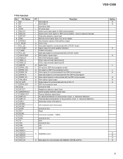
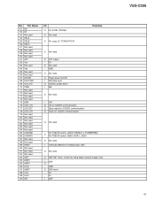
VSX-C300 • Pin Function No. Pin Name 1 G2 2 G1 3 NC 4 ACIN 5...the DSP microcomputer O FAN rotation signal output O Strobe signal for communicate with the E-VOL IC O DSP microcomputer reset − Connect to Vdd I Headphone detection signal input I Center speaker detection signal input I Thermal detection signal ...protection circuit (L: Abnormal detection) I Destination switch (A/D take-in) I A/D conversion port of key input − Connect to Vss − Reset − − Connect an oscillator 7.2MHz − Connect to Vss − open − Connect to Vss − +5V ...
VSX-C300 • Pin Function No. Pin Name 1 G2 2 G1 3 NC 4 ACIN 5...the DSP microcomputer O FAN rotation signal output O Strobe signal for communicate with the E-VOL IC O DSP microcomputer reset − Connect to Vdd I Headphone detection signal input I Center speaker detection signal input I Thermal detection signal ...protection circuit (L: Abnormal detection) I Destination switch (A/D take-in) I A/D conversion port of key input − Connect to Vss − Reset − − Connect an oscillator 7.2MHz − Connect to Vss − open − Connect to Vss − +5V ...
Service Manual
Page 60
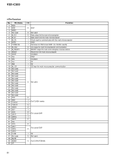
... Name 1 ASO 2 ACK 3 AREQ 4 Not used 5 M_DO 6 M_DI 7 M_CK 8 BYTE 9 T-PGM/OE 10 M_CS2 11 M_READY 12 RESET 13 XOUT 14 Vss 15 XIN 16 Vcc 17 NMI 18 M_CS1 19 Not used 20 Not used 21 Not used 22 Not used 23 ...microcomputer communication O READY output for main microcomputer communication − Reset from the main microcomputer − Oscillator − GND − Oscillator − 5V I 5V I CS input for main microcomputer communication O Not used O I For FLASH rewrite I O O I O For crystal DSP O I O O For crystal DSP O I 5V O Not used O For E-SW (TC9164) 60 VSX-C300 • Pin Function No.
... Name 1 ASO 2 ACK 3 AREQ 4 Not used 5 M_DO 6 M_DI 7 M_CK 8 BYTE 9 T-PGM/OE 10 M_CS2 11 M_READY 12 RESET 13 XOUT 14 Vss 15 XIN 16 Vcc 17 NMI 18 M_CS1 19 Not used 20 Not used 21 Not used 22 Not used 23 ...microcomputer communication O READY output for main microcomputer communication − Reset from the main microcomputer − Oscillator − GND − Oscillator − 5V I 5V I CS input for main microcomputer communication O Not used O I For FLASH rewrite I O O I O For crystal DSP O I O O For crystal DSP O I 5V O Not used O For E-SW (TC9164) 60 VSX-C300 • Pin Function No.
Service Manual
Page 61
... O Not used For TC9215 control (SW H: PASSIV, L: POWERRED) O For TC9215 control (SB H: DSP, L: 6CH) O Not used I Overload detection of analog input (A/D) O Not used O DSP INIT reset (control at rising edge of power supply only) I DSP O − GND O DSP reset − 5V − 5V I DSP VSX-C300 61 No.
... O Not used For TC9215 control (SW H: PASSIV, L: POWERRED) O For TC9215 control (SB H: DSP, L: 6CH) O Not used I Overload detection of analog input (A/D) O Not used O DSP INIT reset (control at rising edge of power supply only) I DSP O − GND O DSP reset − 5V − 5V I DSP VSX-C300 61 No.
