
User Guide
Page 1
... Beach, CA 90801-1760, U.S.A. RF DEMODULATOR RFD-1 ORDER NO. SAFETY INFORMATION 2 2. ZZY APR. 1999 Printed in Japan RRV2125 THIS MANUAL IS APPLICABLE TO THE FOLLOWING MODEL(S) AND TYPE(S). EXPLODED VIEWS AND PARTS LIST 3 3. PCB PARTS LIST 13 6. P.O. LTD. 253 Alexandra Road, #04-01, Singapore 159936 PIONEER ELECTRONIC CORPORATION 1999 T - PIONEER ELECTRONIC (EUROPE) N.V. BLOCK DIAGRAM...
... Beach, CA 90801-1760, U.S.A. RF DEMODULATOR RFD-1 ORDER NO. SAFETY INFORMATION 2 2. ZZY APR. 1999 Printed in Japan RRV2125 THIS MANUAL IS APPLICABLE TO THE FOLLOWING MODEL(S) AND TYPE(S). EXPLODED VIEWS AND PARTS LIST 3 3. PCB PARTS LIST 13 6. P.O. LTD. 253 Alexandra Road, #04-01, Singapore 159936 PIONEER ELECTRONIC CORPORATION 1999 T - PIONEER ELECTRONIC (EUROPE) N.V. BLOCK DIAGRAM...
User Guide
Page 7
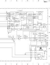
...(1/6 -6/6) : 5 6 TC74HCU04AF V+5V 1 10 14 3 4 13 12 7 GND 1 2 9 8 V+5V JA5 COAXIAL OUT JA4 OPTICAL C OUT 3 21 CN6 1 CN11 1 B LED ASSY D4 GND 2 2 OPTICAL 3 3 D 4 4 GND COAXIAL S2 7 5 6 7 8 5 6 7 8 RFD-1 A CPIN 82 CMIN 83 DOUT 88 DOUTB 89 V+5V 86 GND PDO 63 VI 55 VO 56 MUTE 79 IC1 : PM4007A...
...(1/6 -6/6) : 5 6 TC74HCU04AF V+5V 1 10 14 3 4 13 12 7 GND 1 2 9 8 V+5V JA5 COAXIAL OUT JA4 OPTICAL C OUT 3 21 CN6 1 CN11 1 B LED ASSY D4 GND 2 2 OPTICAL 3 3 D 4 4 GND COAXIAL S2 7 5 6 7 8 5 6 7 8 RFD-1 A CPIN 82 CMIN 83 DOUT 88 DOUTB 89 V+5V 86 GND PDO 63 VI 55 VO 56 MUTE 79 IC1 : PM4007A...
User Guide
Page 14
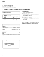
... POWER switch Provides electrical power to the unit. 2 DIGITAL IN switch Use to be shown in this chapter. 7. RFD-1 6. Accessories Power cord (ADG1127) 14 ADJUSTMENT There is being demodulated. SPECIFICATIONS General Power requirements AC 220-230 V, 50/60 Hz Power conpsumption 6 W Weight 1.1 kg Dimentions 202 (W) ... Power cord 1 NOTE: Specifications and design are trademarks of the DIGITAL IN terminals to use (either COAXIAL or OPTICAL). 3 DEMODULATE indicator When lighted, indicates that the input signal supplied to the Dolby Digital (AC-3) RF IN terminal is no information to ...
... POWER switch Provides electrical power to the unit. 2 DIGITAL IN switch Use to be shown in this chapter. 7. RFD-1 6. Accessories Power cord (ADG1127) 14 ADJUSTMENT There is being demodulated. SPECIFICATIONS General Power requirements AC 220-230 V, 50/60 Hz Power conpsumption 6 W Weight 1.1 kg Dimentions 202 (W) ... Power cord 1 NOTE: Specifications and design are trademarks of the DIGITAL IN terminals to use (either COAXIAL or OPTICAL). 3 DEMODULATE indicator When lighted, indicates that the input signal supplied to the Dolby Digital (AC-3) RF IN terminal is no information to ...