
User Guide
Page 1
... Model RFD-1 O Power Requirement AC220 - 230V Remarks CONTENTS 1. BLOCK DIAGRAM AND SCHEMATIC DIAGRAM 6 4. P.O. LTD. 253 Alexandra Road, #04-01, Singapore 159936 PIONEER ELECTRONIC CORPORATION 1999 T - EXPLODED VIEWS AND PARTS LIST 3 3. ADJUSTMENT 14 7. PANEL FACILITIES AND SPECIFICATIONS ..... 14 PIONEER ELECTRONIC CORPORATION 4-1, Meguro 1-Chome, Meguro-ku, Tokyo 153-8654, Japan PIONEER ELECTRONICS SERVICE, INC. PIONEER ELECTRONIC (EUROPE) N.V. RF DEMODULATOR RFD-1 ORDER NO. Box 1760, Long Beach, CA 90801-1760, U.S.A. RRV2125 THIS MANUAL...
... Model RFD-1 O Power Requirement AC220 - 230V Remarks CONTENTS 1. BLOCK DIAGRAM AND SCHEMATIC DIAGRAM 6 4. P.O. LTD. 253 Alexandra Road, #04-01, Singapore 159936 PIONEER ELECTRONIC CORPORATION 1999 T - EXPLODED VIEWS AND PARTS LIST 3 3. ADJUSTMENT 14 7. PANEL FACILITIES AND SPECIFICATIONS ..... 14 PIONEER ELECTRONIC CORPORATION 4-1, Meguro 1-Chome, Meguro-ku, Tokyo 153-8654, Japan PIONEER ELECTRONICS SERVICE, INC. PIONEER ELECTRONIC (EUROPE) N.V. RF DEMODULATOR RFD-1 ORDER NO. Box 1760, Long Beach, CA 90801-1760, U.S.A. RRV2125 THIS MANUAL...
User Guide
Page 2
... adversely affect the safety and reliability of , PIONEER Service Manual may void the warranty. Electrical components having such features are often not evident from time to , or additional copies of the product and may be of the appliance directly into a 120V AC 60Hz outlet and turn the AC power switch on PCB indicate that replacement parts must not exceed 0.5mA. PRODUCT SAFETY NOTICE...
... adversely affect the safety and reliability of , PIONEER Service Manual may void the warranty. Electrical components having such features are often not evident from time to , or additional copies of the product and may be of the appliance directly into a 120V AC 60Hz outlet and turn the AC power switch on PCB indicate that replacement parts must not exceed 0.5mA. PRODUCT SAFETY NOTICE...
User Guide
Page 3
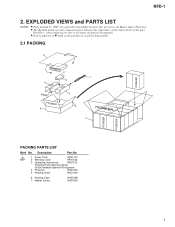
NSP 1 Power Cord ADG1127 2 Warranty Card ARY7022 3 Operating Instructions ARE7212 (English/French/German/Italian /Dutch/Swedish/Spanish/Portuguese) 4 Protector DHA1235 5 Packing Sheet RHC1050 6 Packing Case 7 Master Carton AHG7058 AHG7060 3 Description Part No. Therefore, when replacing, be sure to use parts of identical designation. • Screws adjacent to mark on the product are not in our Master Spare Parts List. • The mark found...
NSP 1 Power Cord ADG1127 2 Warranty Card ARY7022 3 Operating Instructions ARE7212 (English/French/German/Italian /Dutch/Swedish/Spanish/Portuguese) 4 Protector DHA1235 5 Packing Sheet RHC1050 6 Packing Case 7 Master Carton AHG7058 AHG7060 3 Description Part No. Therefore, when replacing, be sure to use parts of identical designation. • Screws adjacent to mark on the product are not in our Master Spare Parts List. • The mark found...
User Guide
Page 5
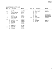
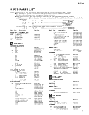
(1) EXTERIOR PARTS LIST Mark No. AEC7225 AXA7072 ARW7036 BBZ30P060FZK BBZ30P080FCC PMA30P060FMC ZCB-069Z VRW1727 DNK2331 5 Description 21 Cushion 22 Front Panel Assy 23 Caution Label 24 25 NSP 26 Screw 27 Screw 28 Screw 29 Cord Stopper 30 31 32 Fuse Label 33 LED Lens Part No. Description...) 5 Housing Assy (3P) Part No. VWR1303 VWV1601 VWY1048 AEK1048 VKP2178 6 Housing Assy (4P) 7 AC Inlet Assy 8 Housing Assy (7P) 9 Power Transformer (AC220-230V) VKP2179 VKP2183 AKP7037 VTT1153 NSP 10 Front Stay 11 Locking Card Spacer 12 Disc Guard 13 Guide Ring 14 Washer 15 Poron Leg...
(1) EXTERIOR PARTS LIST Mark No. AEC7225 AXA7072 ARW7036 BBZ30P060FZK BBZ30P080FCC PMA30P060FMC ZCB-069Z VRW1727 DNK2331 5 Description 21 Cushion 22 Front Panel Assy 23 Caution Label 24 25 NSP 26 Screw 27 Screw 28 Screw 29 Cord Stopper 30 31 32 Fuse Label 33 LED Lens Part No. Description...) 5 Housing Assy (3P) Part No. VWR1303 VWV1601 VWY1048 AEK1048 VKP2178 6 Housing Assy (4P) 7 AC Inlet Assy 8 Housing Assy (7P) 9 Power Transformer (AC220-230V) VKP2179 VKP2183 AKP7037 VTT1153 NSP 10 Front Stay 11 Locking Card Spacer 12 Disc Guard 13 Guide Ring 14 Washer 15 Poron Leg...
User Guide
Page 6
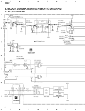
1 2 3 4 RFD-1 3. BLOCK DIAGRAM and SCHEMATIC DIAGRAM 3.1 BLOCK DIAGRAM A • AC MODE CN1 GND AC-3 RF IN GND V+5V B Q4 2SC2412K 70mVp-p V+5V Q1 IC3 (1/2) : 2SC2412K 23+ MC14577CF 8 1 4 GND GND B.P.F Q2 Q3 2SC2412K 2SA1037K GND GND GND V-5V : RF Signal Route IC3 (2/2) : MC14577CF 67 5+ Q6 2SA1037K V+5V GND + - + - IC4 (1/2) : 82 GND BA4560F... : TC74HC08AF V+5V 4 6 5 12 3 GND V+5V V+5V 1 3 2 CN2 S1 CN3 CN4 FU1 1 11 2 22 D AC220 - 230V C SW ASSY POWER TRANSFORMER VTT1153 D203-D206 IC200 LM2940CT-5.0 IC201 NJM79L05 V+5V V-5V 6 1 2 3 4
1 2 3 4 RFD-1 3. BLOCK DIAGRAM and SCHEMATIC DIAGRAM 3.1 BLOCK DIAGRAM A • AC MODE CN1 GND AC-3 RF IN GND V+5V B Q4 2SC2412K 70mVp-p V+5V Q1 IC3 (1/2) : 2SC2412K 23+ MC14577CF 8 1 4 GND GND B.P.F Q2 Q3 2SC2412K 2SA1037K GND GND GND V-5V : RF Signal Route IC3 (2/2) : MC14577CF 67 5+ Q6 2SA1037K V+5V GND + - + - IC4 (1/2) : 82 GND BA4560F... : TC74HC08AF V+5V 4 6 5 12 3 GND V+5V V+5V 1 3 2 CN2 S1 CN3 CN4 FU1 1 11 2 22 D AC220 - 230V C SW ASSY POWER TRANSFORMER VTT1153 D203-D206 IC200 LM2940CT-5.0 IC201 NJM79L05 V+5V V-5V 6 1 2 3 4
User Guide
Page 7
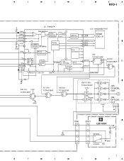
....08MHz Oscillator 46.08MHz Timing Generator D1 - Detection S/P Protection IC2 : HM62256BLFP-8T Address Generator A0 - D7 42 OEB 36 WEB Phase Comparator 9kHz Error Correction IC9 : 1/2048 Divider 1/2 TC74HC123AF MUTO A1 DAI 9.216MHz Controller 66 AC-3 Synchronism 1 DAOUT SW 70 13 Q 4Q IC7(3/4) : TC74HC08AF B 10 8 9 3 RESET 4 OSC ON 90 C9M Serial Data + IC8 (1/2) : V+5V TC74HC32AF...
....08MHz Oscillator 46.08MHz Timing Generator D1 - Detection S/P Protection IC2 : HM62256BLFP-8T Address Generator A0 - D7 42 OEB 36 WEB Phase Comparator 9kHz Error Correction IC9 : 1/2048 Divider 1/2 TC74HC123AF MUTO A1 DAI 9.216MHz Controller 66 AC-3 Synchronism 1 DAOUT SW 70 13 Q 4Q IC7(3/4) : TC74HC08AF B 10 8 9 3 RESET 4 OSC ON 90 C9M Serial Data + IC8 (1/2) : V+5V TC74HC32AF...
User Guide
Page 8
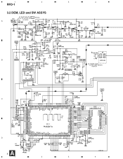
1 2 3 4 RFD-1 3.2 DEM, LED and SW ASSYS 70mVp-p • AC MODE A BA4560F B BA4560F AC POWER CORD : AC220 - 230V, 50/60Hz ADG1127 C D A 8 1 HM62256BLFP-8T 2.5V p-p 2 3 4
1 2 3 4 RFD-1 3.2 DEM, LED and SW ASSYS 70mVp-p • AC MODE A BA4560F B BA4560F AC POWER CORD : AC220 - 230V, 50/60Hz ADG1127 C D A 8 1 HM62256BLFP-8T 2.5V p-p 2 3 4
User Guide
Page 9
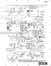
OFF LEDB ASSY S2 :DIGITAL IN OPTICAL - COAXIAL FU1 T250mA 250V (AEK1048) C208 220/10 B C CAPACITOR COVER (VEC-063) SW ASSY (VWR1303) AKP7037 POWER TRANSFORMER VTT1153 B LED ASSY (VWY1048) C 5Vp-p 160nS 5 D • NOTE FOR FUSE REPLACEMENT CAUTION -FOR CONTINUED PROTECTION AGAINST RISK OF FIRE. 5 6 7 8 RFD-1 Note : When ordering service parts, be sure to refer to "EXPLODED VIEWS and PARTS LIST" or "PCB PARTS LIST". 200mV p-p : RF Signal Route A A DEM ASSY (VWV1601) • SWITCHES SW ASSY S1 : POWER ON - A B C9 6 7 8 REPLACE WITH SAME TYPE AND RATINGS ONLY.
OFF LEDB ASSY S2 :DIGITAL IN OPTICAL - COAXIAL FU1 T250mA 250V (AEK1048) C208 220/10 B C CAPACITOR COVER (VEC-063) SW ASSY (VWR1303) AKP7037 POWER TRANSFORMER VTT1153 B LED ASSY (VWY1048) C 5Vp-p 160nS 5 D • NOTE FOR FUSE REPLACEMENT CAUTION -FOR CONTINUED PROTECTION AGAINST RISK OF FIRE. 5 6 7 8 RFD-1 Note : When ordering service parts, be sure to refer to "EXPLODED VIEWS and PARTS LIST" or "PCB PARTS LIST". 200mV p-p : RF Signal Route A A DEM ASSY (VWV1601) • SWITCHES SW ASSY S1 : POWER ON - A B C9 6 7 8 REPLACE WITH SAME TYPE AND RATINGS ONLY.
User Guide
Page 10
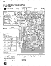
... D G SD G S Field effect transistor Resistor array 3-terminal regulator 3. Viewpoint of PCB and schematic diagrams is shown below. PCB CONNECTION DIAGRAM 4.1 DEM ASSY HOUSING ASSY(AKP7037) A A DEM ASSY 4 B CN11 B C CN3 POWER TRANSFORMER NOTE FOR PCB DIAGRAMS: 1. A comparison between the main parts of PCB diagrams Capacitor Connector D Chip Part SIDE A Q5 Q4 Q1 IC201 IC200 IC5 Q2 IC3 IC9 IC7 Q3...
... D G SD G S Field effect transistor Resistor array 3-terminal regulator 3. Viewpoint of PCB and schematic diagrams is shown below. PCB CONNECTION DIAGRAM 4.1 DEM ASSY HOUSING ASSY(AKP7037) A A DEM ASSY 4 B CN11 B C CN3 POWER TRANSFORMER NOTE FOR PCB DIAGRAMS: 1. A comparison between the main parts of PCB diagrams Capacitor Connector D Chip Part SIDE A Q5 Q4 Q1 IC201 IC200 IC5 Q2 IC3 IC9 IC7 Q3...
User Guide
Page 12
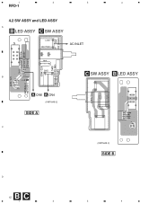
1 2 3 4 RFD-1 4.2 SW ASSY and LED ASSY A B LED ASSY C SW ASSY LIVE NEUTRAL AC INLET B A CN6 A CN4 (VNP1649-C) SIDE A C D B C 12 1 2 C SW ASSY B LED ASSY (VNP1649-C) SIDE B 3 4
1 2 3 4 RFD-1 4.2 SW ASSY and LED ASSY A B LED ASSY C SW ASSY LIVE NEUTRAL AC INLET B A CN6 A CN4 (VNP1649-C) SIDE A C D B C 12 1 2 C SW ASSY B LED ASSY (VNP1649-C) SIDE B 3 4
User Guide
Page 13
... ASSY SWITCH S1 CAPACITOR C213 (0.01µF/AC250V) OTHERS CN3 2P CONNECTOR CN2 2P CONNECTOR CAPACITOR COVER ASG7007 ACG7020 B2P3S-VH-BK B2P3S-VH-E VEC-063 13 B PARTS Description LISTPart No. Mark No. Therefore, when replacing, be sure to use parts of the part. Description Part No. • NOTES: Parts marked ...tolerance is shown by "NSP" are generally unavailable because they are 3 effective digits (such as shown in our Master Spare Parts List. •The mark found on some component parts indicates the importance of the safety factor of identical designation. •When ordering...
... ASSY SWITCH S1 CAPACITOR C213 (0.01µF/AC250V) OTHERS CN3 2P CONNECTOR CN2 2P CONNECTOR CAPACITOR COVER ASG7007 ACG7020 B2P3S-VH-BK B2P3S-VH-E VEC-063 13 B PARTS Description LISTPart No. Mark No. Therefore, when replacing, be sure to use parts of the part. Description Part No. • NOTES: Parts marked ...tolerance is shown by "NSP" are generally unavailable because they are 3 effective digits (such as shown in our Master Spare Parts List. •The mark found on some component parts indicates the importance of the safety factor of identical designation. •When ordering...
User Guide
Page 14
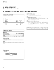
... input signal supplied to the Dolby Digital (AC-3) RF IN terminal is no information to possible modification without notice. "Dolby", "Digital (AC-3)" and the double-D symbol are subject to be shown in this chapter. 7. ADJUSTMENT There is being demodulated. PANEL FACILITIES AND SPECIFICATIONS PANEL FACILITIES 1 2 3 1 POWER switch Provides electrical power to the unit. 2 DIGITAL IN switch Use to select which of Dolby Laboratories Licensing Corporation. Accessories Power cord (ADG1127) 14 RFD...
... input signal supplied to the Dolby Digital (AC-3) RF IN terminal is no information to possible modification without notice. "Dolby", "Digital (AC-3)" and the double-D symbol are subject to be shown in this chapter. 7. ADJUSTMENT There is being demodulated. PANEL FACILITIES AND SPECIFICATIONS PANEL FACILITIES 1 2 3 1 POWER switch Provides electrical power to the unit. 2 DIGITAL IN switch Use to select which of Dolby Laboratories Licensing Corporation. Accessories Power cord (ADG1127) 14 RFD...


