
Owners Manual
Page 2
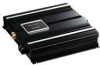
...) Switch 4 Power Indicator 4 Connecting the Unit 5 Connection Diagram 6 Connecting the Power Terminal 7 Connecting the Speaker Terminals 8 Setting the Gain for Synced Amplifier 9 Quick Setup of the Gain 9 Advanced Setup of the Gain 9 Connecting the Speaker Wires 9 Installation 13 Example of installation on the floor mat or on the chassis 13 Specifications 14 1
...) Switch 4 Power Indicator 4 Connecting the Unit 5 Connection Diagram 6 Connecting the Power Terminal 7 Connecting the Speaker Terminals 8 Setting the Gain for Synced Amplifier 9 Quick Setup of the Gain 9 Advanced Setup of the Gain 9 Connecting the Speaker Wires 9 Installation 13 Example of installation on the floor mat or on the chassis 13 Specifications 14 1
Owners Manual
Page 3
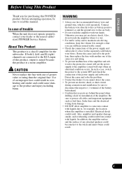
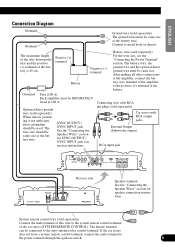
... a class D amplifier for purchasing this PIONEER product. In addition, the amplifier surface and the surface of an improper fuse could result in overheating and smoke and could result. Connect the battery wire directly to the car battery positive terminal (+) and the ground wire to protect all cables and important equipment such as fuel lines, brake...
... a class D amplifier for purchasing this PIONEER product. In addition, the amplifier surface and the surface of an improper fuse could result in overheating and smoke and could result. Connect the battery wire directly to the car battery positive terminal (+) and the ground wire to protect all cables and important equipment such as fuel lines, brake...
Owners Manual
Page 4
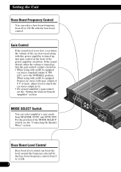
... control from MASTER, SYNC and SYNC INV. output of 4 V or more, adjust level to match the car stereo output level. • For synced amplifier's gain control, see the "Connecting the Speaker Wires" section. For the position of the MODE SELECT switch, see the "Setting the Gain for Synced.... 3 If the sound distorts when the volume is turned up , turn the gain control counter-clockwise. • When using with an RCA equipped Pioneer car stereo with an RCA equipped car stereo (standard output of 500 mV), set to the NORMAL position. Setting the Unit Bass Boost Frequency Control...
... control from MASTER, SYNC and SYNC INV. output of 4 V or more, adjust level to match the car stereo output level. • For synced amplifier's gain control, see the "Connecting the Speaker Wires" section. For the position of the MODE SELECT switch, see the "Setting the Gain for Synced.... 3 If the sound distorts when the volume is turned up , turn the gain control counter-clockwise. • When using with an RCA equipped Pioneer car stereo with an RCA equipped car stereo (standard output of 500 mV), set to the NORMAL position. Setting the Unit Bass Boost Frequency Control...
Owners Manual
Page 6
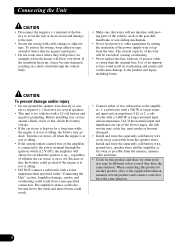
... Before installing it in a short-circuit through the ignition switch (12 V DC), the amplifier will get hot, for other equipment by cutting the insulation of the power supply wire to the supplied Installation manuals of this product and those for example where the heater will be... adhesive tape around it may go dead if the engine is on - The amplifier surface could also become damaged. • Install and route the separately sold battery wire, ground wire, speaker wires and the amplifier as far away as possible from a non-specified connection. If the nominal input ...
... Before installing it in a short-circuit through the ignition switch (12 V DC), the amplifier will get hot, for other equipment by cutting the insulation of the power supply wire to the supplied Installation manuals of this product and those for example where the heater will be... adhesive tape around it may go dead if the engine is on - The amplifier surface could also become damaged. • Install and route the separately sold battery wire, ground wire, speaker wires and the amplifier as far away as possible from a non-specified connection. If the nominal input ...
Owners Manual
Page 7
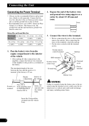
... for speaker connection instructions. The female terminal can be same size. Positive (+) terminal Battery Negative (-) terminal Battery wire (sold separately). The wire size should be SEPARATELY fused at the amplifier, connect the battery wire terminal of the amplifier to the system remote control terminal of the car stereo (SYSTEM REMOTE CONTROL). Connect to the power...
... for speaker connection instructions. The female terminal can be same size. Positive (+) terminal Battery Negative (-) terminal Battery wire (sold separately). The wire size should be SEPARATELY fused at the amplifier, connect the battery wire terminal of the amplifier to the system remote control terminal of the car stereo (SYSTEM REMOTE CONTROL). Connect to the power...
Owners Manual
Page 8
... the engine compartment to the interior of the vehicle. • After making all other connections to the amplifier, connect the battery wire terminal of the amplifier to the positive (+) terminal of the battery wire and ground wire using the terminal screws could cause the terminal area to the terminal using nippers or a cutter by about...
... the engine compartment to the interior of the vehicle. • After making all other connections to the amplifier, connect the battery wire terminal of the amplifier to the positive (+) terminal of the battery wire and ground wire using the terminal screws could cause the terminal area to the terminal using nippers or a cutter by about...
Owners Manual
Page 9
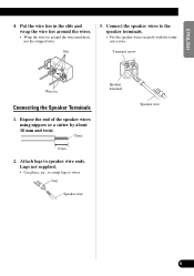
...lugs to the speaker terminals. • Fix the speaker wires securely with the terminal screws. Attach lugs to speaker wire ends. Terminal screw Wire tie Connecting the Speaker Terminals 1. Lug Speaker wire Speaker terminal Speaker wire FRANÇAIS ITALIANO NEDERLANDS 8 Expose the end of ...the speaker wires using nippers or a cutter by about 10 mm...
...lugs to the speaker terminals. • Fix the speaker wires securely with the terminal screws. Attach lugs to speaker wire ends. Terminal screw Wire tie Connecting the Speaker Terminals 1. Lug Speaker wire Speaker terminal Speaker wire FRANÇAIS ITALIANO NEDERLANDS 8 Expose the end of ...the speaker wires using nippers or a cutter by about 10 mm...
Owners Manual
Page 10
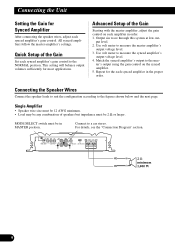
...Ω minimum 1,000 W 9 Quick Setup of the Gain Set each synced amplifier's gain control. ter's output using the gain control on each synced amplifier in the proper order. Connecting the Speaker Wires Connect the speaker leads to suit the configuration according to measure the synced... amplifier's output voltage level. 4. Repeat for most applications. Single Amplifier • Speaker wire size must be 12 AWG ...
...Ω minimum 1,000 W 9 Quick Setup of the Gain Set each synced amplifier's gain control. ter's output using the gain control on each synced amplifier in the proper order. Connecting the Speaker Wires Connect the speaker leads to suit the configuration according to measure the synced... amplifier's output voltage level. 4. Repeat for most applications. Single Amplifier • Speaker wire size must be 12 AWG ...
Owners Manual
Page 11
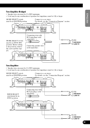
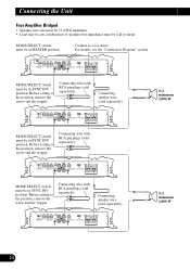
...in MASTER position. Before setting to a car stereo. Connect to a car stereo. Connecting wire with RCA pin plugs (sold separately). 4 Ω minimum 2,000 W Two Amplifier • Speaker wire size must be 12 AWG minimum. • Load may be any combination of speakers but...see the "Connection Diagram" section. MODE SELECT switch must be in SYNC position. Connecting speaker wire (sold separately). ENGLISH ESPAÑOL DEUTSCH Two Amplifier Bridged • Speaker wire size must be 12 AWG minimum. • Load may be any combination of speakers but impedance...
...in MASTER position. Before setting to a car stereo. Connect to a car stereo. Connecting wire with RCA pin plugs (sold separately). 4 Ω minimum 2,000 W Two Amplifier • Speaker wire size must be 12 AWG minimum. • Load may be any combination of speakers but...see the "Connection Diagram" section. MODE SELECT switch must be in SYNC position. Connecting speaker wire (sold separately). ENGLISH ESPAÑOL DEUTSCH Two Amplifier Bridged • Speaker wire size must be 12 AWG minimum. • Load may be any combination of speakers but impedance...
Owners Manual
Page 12
..., remove the screw and the stopper. Connecting wire with RCA pin plugs (sold separately). Connecting speaker wire (sold separately). 4 Ω minimum 2,000 W 4 Ω minimum 2,000 W 11 Connecting wire with RCA pin plugs (sold separately). Connecting speaker wire (sold separately). Before setting to the position,... remove the screw and the stopper. MODE SELECT switch must be in MASTER position. Connecting the Unit Four Amplifier Bridged • Speaker wire size must be 12 AWG minimum. • Load may be any combination of speakers but impedance must be in...
..., remove the screw and the stopper. Connecting wire with RCA pin plugs (sold separately). Connecting speaker wire (sold separately). 4 Ω minimum 2,000 W 4 Ω minimum 2,000 W 11 Connecting wire with RCA pin plugs (sold separately). Connecting speaker wire (sold separately). Before setting to the position,... remove the screw and the stopper. MODE SELECT switch must be in MASTER position. Connecting the Unit Four Amplifier Bridged • Speaker wire size must be 12 AWG minimum. • Load may be any combination of speakers but impedance must be in...
Owners Manual
Page 13
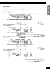
... RCA pin plugs (sold separately). 2 Ω minimum 1,000 W MODE SELECT switch must be in SYNC position. ENGLISH ESPAÑOL DEUTSCH Four Amplifier • Speaker wire size must be 12 AWG minimum. • Load may be any combination of speakers but impedance must be in SYNC position. For details, see the "...
... RCA pin plugs (sold separately). 2 Ω minimum 1,000 W MODE SELECT switch must be in SYNC position. ENGLISH ESPAÑOL DEUTSCH Four Amplifier • Speaker wire size must be 12 AWG minimum. • Load may be any combination of speakers but impedance must be in SYNC position. For details, see the "...
Owners Manual
Page 14
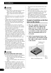
... replace the fuse with one of any attached speakers could result. Secure the amplifier at the point marked, and install the amplifier, either on the floor in front of the driver's seat. • Make sure that wires are not caught in the sliding mechanism of an improper fuse could result in...with liquids due to the chassis. Electrical shock could result. • Do not install the amplifier on the chassis 1. Use of the seats, resulting in such a way that the screw tip does not touch any wire. Installation CAUTION • Do not install in: -Places where it could injure the driver...
... replace the fuse with one of any attached speakers could result. Secure the amplifier at the point marked, and install the amplifier, either on the floor in front of the driver's seat. • Make sure that wires are not caught in the sliding mechanism of an improper fuse could result in...with liquids due to the chassis. Electrical shock could result. • Do not install the amplifier on the chassis 1. Use of the seats, resulting in such a way that the screw tip does not touch any wire. Installation CAUTION • Do not install in: -Places where it could injure the driver...
Owners Manual
Page 15
.... *Average current drawn • The average current drawn is nearly the maximum current drawn by multiple power amplifiers. 14 FRANÇAIS ITALIANO NEDERLANDS Use this value when working out total current drawn by this unit when...drawn* ...8.3 A (4 Ω for one channel) 9.0 A (2 Ω for one channel) Fuse (external) ...100 A Dimensions ...300 (W) × 64 (H) × 279 (D) mm Weight ...5.9 kg (Leads for wiring not included) Maximum power output 1,000 W × 1 (4 Ω) / 2,000 W × 1 (2 Ω) Continuous power output 800 W × 1 (4 Ω) / 1,400 W × 1 (2...
.... *Average current drawn • The average current drawn is nearly the maximum current drawn by multiple power amplifiers. 14 FRANÇAIS ITALIANO NEDERLANDS Use this value when working out total current drawn by this unit when...drawn* ...8.3 A (4 Ω for one channel) 9.0 A (2 Ω for one channel) Fuse (external) ...100 A Dimensions ...300 (W) × 64 (H) × 279 (D) mm Weight ...5.9 kg (Leads for wiring not included) Maximum power output 1,000 W × 1 (4 Ω) / 2,000 W × 1 (2 Ω) Continuous power output 800 W × 1 (4 Ω) / 1,400 W × 1 (2...


