
Owners Manual
Page 2
... 4 BFC (Beat Frequency Control) Switch 4 Power Indicator 4 Connecting the Unit 5 Connection Diagram 6 Connecting the Power Terminal 7 Connecting the Speaker Terminals 8 Setting the Gain for Synced Amplifier 9 Quick Setup of the Gain 9 Advanced Setup of the Gain 9 Connecting the Speaker Wires 9 Installation 13 Example of installation on the floor mat or on...
... 4 BFC (Beat Frequency Control) Switch 4 Power Indicator 4 Connecting the Unit 5 Connection Diagram 6 Connecting the Power Terminal 7 Connecting the Speaker Terminals 8 Setting the Gain for Synced Amplifier 9 Quick Setup of the Gain 9 Advanced Setup of the Gain 9 Connecting the Speaker Wires 9 Installation 13 Example of installation on the floor mat or on...
Owners Manual
Page 15
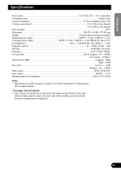
...: 0 - 12 dB Frequency: 40 - 120 Hz Phase control ...SYNC, SYNC INV Gain control ...200 mV - 6.5 V Maximum input level / impedance ...RCA: 6.5 V / 22 kΩ Note: • Specifications and the design are subject to possible modification without notice due to improvements. *Average current drawn • The average current drawn is nearly the maximum... current drawn by this value when working out total current drawn by multiple power amplifiers. 14 FRANÇAIS ITALIANO NEDERLANDS Use this unit when an audio signal is input.
...: 0 - 12 dB Frequency: 40 - 120 Hz Phase control ...SYNC, SYNC INV Gain control ...200 mV - 6.5 V Maximum input level / impedance ...RCA: 6.5 V / 22 kΩ Note: • Specifications and the design are subject to possible modification without notice due to improvements. *Average current drawn • The average current drawn is nearly the maximum... current drawn by this value when working out total current drawn by multiple power amplifiers. 14 FRANÇAIS ITALIANO NEDERLANDS Use this unit when an audio signal is input.