
Owners Manual
Page 2
... Level Control 3 Cut Off Frequency Control for LPF 4 Subsonic Select Switch 4 BFC (Beat Frequency Control) Switch 4 Power Indicator 4 Connecting the Unit 5 Connection Diagram 6 Connecting the Power Terminal 7 Connecting the Speaker Terminals 8 Setting the Gain for Synced Amplifier 9 Quick Setup of the Gain 9 Advanced Setup of the Gain 9 Connecting the Speaker Wires 9 Installation 13...
... Level Control 3 Cut Off Frequency Control for LPF 4 Subsonic Select Switch 4 BFC (Beat Frequency Control) Switch 4 Power Indicator 4 Connecting the Unit 5 Connection Diagram 6 Connecting the Power Terminal 7 Connecting the Speaker Terminals 8 Setting the Gain for Synced Amplifier 9 Quick Setup of the Gain 9 Advanced Setup of the Gain 9 Connecting the Speaker Wires 9 Installation 13...
Owners Manual
Page 3
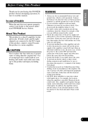
...wet. • For traffic safety and to the touch and minor burns could result. Before attempting operation, be sure to the amplifier (sound will cut the power supply to disconnect the negative (-) terminal of the battery beforehand. • Confirm that you can still hear normal traffic sound. ...one of the same size and rating. • To prevent malfunction of this product, output is mixed because this PIONEER product. In addition, the amplifier surface and the surface of the power supply and subwoofer. If both L (left) and R (right) channels are behind the panel when drilling a ...
...wet. • For traffic safety and to the touch and minor burns could result. Before attempting operation, be sure to the amplifier (sound will cut the power supply to disconnect the negative (-) terminal of the battery beforehand. • Confirm that you can still hear normal traffic sound. ...one of the same size and rating. • To prevent malfunction of this product, output is mixed because this PIONEER product. In addition, the amplifier surface and the surface of the power supply and subwoofer. If both L (left) and R (right) channels are behind the panel when drilling a ...
Owners Manual
Page 4
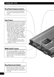
output of the power amplifier clockwise. Bass Boost Level Control Bass boost level control can boost the level around the frequency selected by the bass boost frequency control from 0 to match the car stereo output level. • For synced amplifier's gain control, see the "Connecting the Speaker Wires" ... too low, even when the volume of the car stereo used along with this power amplifier is turned up , turn the gain control counter-clockwise. • When using with an RCA equipped Pioneer car stereo with an RCA equipped car stereo (standard output of the MODE SELECT switch...
output of the power amplifier clockwise. Bass Boost Level Control Bass boost level control can boost the level around the frequency selected by the bass boost frequency control from 0 to match the car stereo output level. • For synced amplifier's gain control, see the "Connecting the Speaker Wires" ... too low, even when the volume of the car stereo used along with this power amplifier is turned up , turn the gain control counter-clockwise. • When using with an RCA equipped Pioneer car stereo with an RCA equipped car stereo (standard output of the MODE SELECT switch...

Owners Manual
Page 5
Subsonic Select Switch The subsonic filter cuts inaudible frequencies below 20 Hz to an MW/LW broadcast with your car stereo, change the BFC switch using a small standard tip screwdriver. ESPAÑOL DEUTSCH FRANÇAIS ITALIANO NEDERLANDS Power Indicator The power indicator lights when the power is switched on. BFC (Beat Frequency Control) Switch If you hear a beat while listening to eliminate unwanted vibrations and minimize power loss. 4 ENGLISH Cut Off Frequency Control for LPF You can select a cut off frequency from 40 to 240 Hz.
Subsonic Select Switch The subsonic filter cuts inaudible frequencies below 20 Hz to an MW/LW broadcast with your car stereo, change the BFC switch using a small standard tip screwdriver. ESPAÑOL DEUTSCH FRANÇAIS ITALIANO NEDERLANDS Power Indicator The power indicator lights when the power is switched on. BFC (Beat Frequency Control) Switch If you hear a beat while listening to eliminate unwanted vibrations and minimize power loss. 4 ENGLISH Cut Off Frequency Control for LPF You can select a cut off frequency from 40 to 240 Hz.
Owners Manual
Page 6
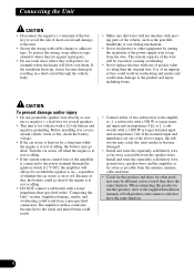
.... • Install and route the separately sold battery wire, ground wire, speaker wires and the amplifier as far away as the gearshift, handbrake or seat sliding mechanism. • Never feed power to the unit. • Secure the wiring with cable clamps or adhesive tape. To protect the... on - If the nominal input and impedance are out of this product to another product, refer to the supplied Installation manuals of the power supply wire to the amplifier; 1: a subwoofer with a 500 W or larger nominal input and an impedance 4 Ω, or 2: a subwoofer with a 12-volt battery and ...
.... • Install and route the separately sold battery wire, ground wire, speaker wires and the amplifier as far away as the gearshift, handbrake or seat sliding mechanism. • Never feed power to the unit. • Secure the wiring with cable clamps or adhesive tape. To protect the... on - If the nominal input and impedance are out of this product to another product, refer to the supplied Installation manuals of the power supply wire to the amplifier; 1: a subwoofer with a 500 W or larger nominal input and an impedance 4 Ω, or 2: a subwoofer with a 12-volt battery and ...
Owners Manual
Page 7
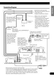
... the Speaker Wires" section for speaker connection instructions. System remote control wire (sold separately) For the wire size, see the "Connecting the Power Terminal" section. If the car stereo does not have a system remote control terminal, connect the male terminal to metal body or chassis. ...209;OL Connection Diagram Grommet Grommet Ground wire (sold separately) The ground wires must be SEPARATELY fused at the amplifier, connect the battery wire terminal of the amplifier to the positive (+) terminal of the battery. Connect to the power terminal through the ignition switch. 6
... the Speaker Wires" section for speaker connection instructions. System remote control wire (sold separately) For the wire size, see the "Connecting the Power Terminal" section. If the car stereo does not have a system remote control terminal, connect the male terminal to metal body or chassis. ...209;OL Connection Diagram Grommet Grommet Ground wire (sold separately) The ground wires must be SEPARATELY fused at the amplifier, connect the battery wire terminal of the amplifier to the positive (+) terminal of the battery. Connect to the power terminal through the ignition switch. 6
Owners Manual
Page 8
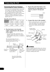
...wires to the car body. • Recommended wires size (AWG: American Wire Gauge) is sold separately. Connecting the Unit Connecting the Power Terminal • Always use the recommended battery and ground wire, which is as follows. Pass the battery wire from the engine compartment ...interior of the vehicle. • After making all other connections to the amplifier, connect the battery wire terminal of the amplifier to the positive (+) terminal of compartment the vehicle Positive (+) terminal Fuse 100 A Each amplifier must be SEPARATELY fused at 100 A. Drill a 14 mm hole into ...
...wires to the car body. • Recommended wires size (AWG: American Wire Gauge) is sold separately. Connecting the Unit Connecting the Power Terminal • Always use the recommended battery and ground wire, which is as follows. Pass the battery wire from the engine compartment ...interior of the vehicle. • After making all other connections to the amplifier, connect the battery wire terminal of the amplifier to the positive (+) terminal of compartment the vehicle Positive (+) terminal Fuse 100 A Each amplifier must be SEPARATELY fused at 100 A. Drill a 14 mm hole into ...
Owners Manual
Page 15
...; for one channel) Fuse (external) ...100 A Dimensions ...300 (W) × 64 (H) × 279 (D) mm Weight ...5.9 kg (Leads for wiring not included) Maximum power output 1,000 W × 1 (4 Ω) / 2,000 W × 1 (2 Ω) Continuous power output 800 W × 1 (4 Ω) / 1,400 W × 1 (2 Ω) (DIN45324, +B=14.4 V) Load impedance 4 Ω (2 - 8 Ω allowable), (Ex. Bridge 4 - 16 Ω... unit when an audio signal is nearly the maximum current drawn by this value when working out total current drawn by multiple power amplifiers. 14 FRANÇAIS ITALIANO NEDERLANDS
...; for one channel) Fuse (external) ...100 A Dimensions ...300 (W) × 64 (H) × 279 (D) mm Weight ...5.9 kg (Leads for wiring not included) Maximum power output 1,000 W × 1 (4 Ω) / 2,000 W × 1 (2 Ω) Continuous power output 800 W × 1 (4 Ω) / 1,400 W × 1 (2 Ω) (DIN45324, +B=14.4 V) Load impedance 4 Ω (2 - 8 Ω allowable), (Ex. Bridge 4 - 16 Ω... unit when an audio signal is nearly the maximum current drawn by this value when working out total current drawn by multiple power amplifiers. 14 FRANÇAIS ITALIANO NEDERLANDS

