Owner's Manual
Page 2
... Connecting the Speaker Output Terminals ...... 8 Connecting the Power Terminal 9 Setting the Gain for synced amplifier 10 Connecting the Speaker Wires 10 Installation 15 Attaching the Bass boost remote control ........ 15 Example of installation on the floor mat or on the chassis 16 Replacing the terminal ...cover 16 Changing the Direction of the unit. Important The serial number of this amplifier is written on the enclosed warranty card. After-sales service for Pioneer ...
... Connecting the Speaker Output Terminals ...... 8 Connecting the Power Terminal 9 Setting the Gain for synced amplifier 10 Connecting the Speaker Wires 10 Installation 15 Attaching the Bass boost remote control ........ 15 Example of installation on the floor mat or on the chassis 16 Replacing the terminal ...cover 16 Changing the Direction of the unit. Important The serial number of this amplifier is written on the enclosed warranty card. After-sales service for Pioneer ...
Owner's Manual
Page 4
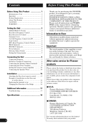
..."Connecting the Speaker Wires" section for LPF You can select a bass boost level from 40 Hz to the amplifier, see the "Connection Diagram" section. 3 Cut Off Frequency Control for details on the MODE SELECT switch. Set the MODE SELECT switch to the MASTER position when using synchronously... or more of connecting the bass boost remote control to 240 Hz. Bass Boost Level Control You can select a cut off frequency from 0, 6, 9 and 12 dB. For instruction of these amplifiers in which they are connected. When using one amplifier only. Terminal Cover Before setting up the unit...
..."Connecting the Speaker Wires" section for LPF You can select a bass boost level from 40 Hz to the amplifier, see the "Connection Diagram" section. 3 Cut Off Frequency Control for details on the MODE SELECT switch. Set the MODE SELECT switch to the MASTER position when using synchronously... or more of connecting the bass boost remote control to 240 Hz. Bass Boost Level Control You can select a cut off frequency from 0, 6, 9 and 12 dB. For instruction of these amplifiers in which they are connected. When using one amplifier only. Terminal Cover Before setting up the unit...
Owner's Manual
Page 5
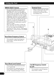
... more, adjust level to an AM broadcast with the amplifier. See the "Troubleshooting" section on page 17 for synced amplifier" section. If the sound distorts when the volume is turned up , turn the gain control counter-clockwise. • When using with an RCA equipped Pioneer car stereo with max. See the "Troubleshooting" section on...
... more, adjust level to an AM broadcast with the amplifier. See the "Troubleshooting" section on page 17 for synced amplifier" section. If the sound distorts when the volume is turned up , turn the gain control counter-clockwise. • When using with an RCA equipped Pioneer car stereo with max. See the "Troubleshooting" section on...
Owner's Manual
Page 6
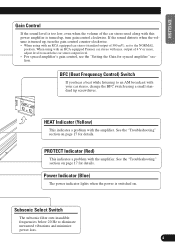
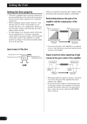
... from time to time, contact the nearest authorized PIONEER Service Station. 5 Preout level: 4 V Preout level: 6.5 V Preout level: 2 V (Standard: 500 mV) Signal waveform when outputting at high volume by the gain control of the amplifier Normal gain Equal power Maximum gain Signal waveform Amplifier gain (normal) Signal waveform Amplifier gain (maximum) • With high output the...
... from time to time, contact the nearest authorized PIONEER Service Station. 5 Preout level: 4 V Preout level: 6.5 V Preout level: 2 V (Standard: 500 mV) Signal waveform when outputting at high volume by the gain control of the amplifier Normal gain Equal power Maximum gain Signal waveform Amplifier gain (normal) Signal waveform Amplifier gain (maximum) • With high output the...
Owner's Manual
Page 7
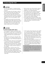
.... • This unit is recommended. • Make sure that wires will not interfere with one of an improper fuse could cause damage to the amplifier; 1: a subwoofer with a 750 W or larger nominal input and an impedance 4 Ω, 2: a subwoofer with a 1 500 W or larger...amplifier. Amplifier damage, smoke, and overheating could go dead. To protect the wiring, wrap adhesive tape around it in overheating and smoke and could result in a recreational vehicle, truck or bus, check the battery voltage. • If the car stereo is at rest or idling. • If the system remote control...
.... • This unit is recommended. • Make sure that wires will not interfere with one of an improper fuse could cause damage to the amplifier; 1: a subwoofer with a 750 W or larger nominal input and an impedance 4 Ω, 2: a subwoofer with a 1 500 W or larger...amplifier. Amplifier damage, smoke, and overheating could go dead. To protect the wiring, wrap adhesive tape around it in overheating and smoke and could result in a recreational vehicle, truck or bus, check the battery voltage. • If the car stereo is at rest or idling. • If the system remote control...
Owner's Manual
Page 8
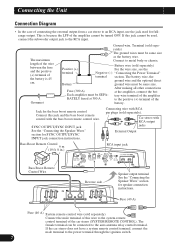
... the case of the battery. to the positive (+) terminal of connecting the external output from a car stereo to the system remote control terminal of the amplifier cannot be SEPA- This is 45 cm. After making all other connections Fuse (300 A) at 300 A. If the car stereo...an RCA input, use the jack used , connect the subwoofer output jack to the auto-antenna relay control terminal. Each amplifier must be turned OFF. Fuse (40 A) Fuse (40 A) System remote control wire (sold separately) Positive (+) For the wire size, see the terminal Negative (-) "Connecting the Power...
... the case of the battery. to the positive (+) terminal of connecting the external output from a car stereo to the system remote control terminal of the amplifier cannot be SEPA- This is 45 cm. After making all other connections Fuse (300 A) at 300 A. If the car stereo...an RCA input, use the jack used , connect the subwoofer output jack to the auto-antenna relay control terminal. Each amplifier must be turned OFF. Fuse (40 A) Fuse (40 A) System remote control wire (sold separately) Positive (+) For the wire size, see the terminal Negative (-) "Connecting the Power...
Owner's Manual
Page 9
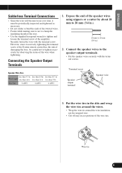
...output terminals. • Fix the speaker wires securely with the terminal screw. However, since excessively tightening the terminal screw of the System remote control has the risk of damaging the wire, be periodically inspected and tightened as necessary. • Do not solder or bind the ends of the... to not to clamp the insulating sheath of the wire. • Use the supplied hexagonal wrench to tighten and loosen the terminal screw of the amplifier. less than 14 ft. Put the wire ties in .) 2. Wire tie 8 less than 21 ft. Terminal screw Speaker output terminal Speaker wire 3....
...output terminals. • Fix the speaker wires securely with the terminal screw. However, since excessively tightening the terminal screw of the System remote control has the risk of damaging the wire, be periodically inspected and tightened as necessary. • Do not solder or bind the ends of the... to not to clamp the insulating sheath of the wire. • Use the supplied hexagonal wrench to tighten and loosen the terminal screw of the amplifier. less than 14 ft. Put the wire ties in .) 2. Wire tie 8 less than 21 ft. Terminal screw Speaker output terminal Speaker wire 3....
Owner's Manual
Page 10
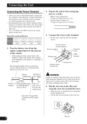
.... Pass the battery wire from the engine compartment to the interior of the vehicle. • After making all other connections to the amplifier, connect the battery wire terminal of the amplifier to 25 mm (7/8 in .) 3. Insert the O-ring rubber grommet into the vehicle body. to 16 mm (1/2 in the slits and... terminal be same size. • Use a 10 AWG to overheat and could cause the terminal area to 20 AWG wire for the system remote control wire. The maximum length of the wire between the fuse and the positive (+) terminal of wires using the terminal screws could result in .) hole ...
.... Pass the battery wire from the engine compartment to the interior of the vehicle. • After making all other connections to the amplifier, connect the battery wire terminal of the amplifier to 25 mm (7/8 in .) 3. Insert the O-ring rubber grommet into the vehicle body. to 16 mm (1/2 in the slits and... terminal be same size. • Use a 10 AWG to overheat and could cause the terminal area to 20 AWG wire for the system remote control wire. The maximum length of the wire between the fuse and the positive (+) terminal of wires using the terminal screws could result in .) hole ...
Owner's Manual
Page 11
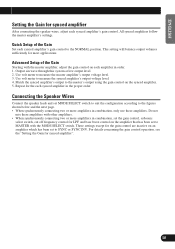
... through this system at low output level. 2. Match the synced amplifier's output to the master's output using the gain control on the amplifier that has been set the gain control, subsonic select switch, cut off frequency control for the gain control are inactive on each synced amplifier's gain control. This setting will balance output volumes sufficiently for synced...
... through this system at low output level. 2. Match the synced amplifier's output to the master's output using the gain control on the amplifier that has been set the gain control, subsonic select switch, cut off frequency control for the gain control are inactive on each synced amplifier's gain control. This setting will balance output volumes sufficiently for synced...
Owner's Manual
Page 16
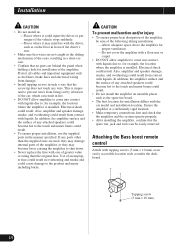
... installed. Electrical shock could result. Attaching the Bass boost remote control Attach with tapping screws (3 mm × 10 mm) at a sufficiently rigid location. • Make temporary connections first and check that the amplifier and the system operate properly. • After installing the amplifier, confirm that the spare tire, jack and tools can result...
... installed. Electrical shock could result. Attaching the Bass boost remote control Attach with tapping screws (3 mm × 10 mm) at a sufficiently rigid location. • Make temporary connections first and check that the amplifier and the system operate properly. • After installing the amplifier, confirm that the spare tire, jack and tools can result...
Owner's Manual
Page 19
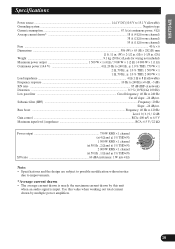
Bass boost ...Frequency: 40 Hz to 120 Hz Level: 0 / 6 / 9 / 12 dB Gain control ...RCA: 400 mV to 6.5 V Maximum input level / impedance ...RCA: 6.5 V / 22 kΩ Power output 750 W RMS × 1 channel (at 4 Ω and 1% THD+N) 1 500 W RMS × 1 channel .... Use this unit when an audio signal is nearly the maximum current drawn by this value when working out total current drawn by multiple power amplifiers. 18 ENGLISH ESPAÑOL DEUTSCH FRANÇAIS ITALIANO NEDERLANDS Specifications Power source ...14.4 V DC (10.8 V to 15.1 V allowable) Grounding system ...Negative type ...
Bass boost ...Frequency: 40 Hz to 120 Hz Level: 0 / 6 / 9 / 12 dB Gain control ...RCA: 400 mV to 6.5 V Maximum input level / impedance ...RCA: 6.5 V / 22 kΩ Power output 750 W RMS × 1 channel (at 4 Ω and 1% THD+N) 1 500 W RMS × 1 channel .... Use this unit when an audio signal is nearly the maximum current drawn by this value when working out total current drawn by multiple power amplifiers. 18 ENGLISH ESPAÑOL DEUTSCH FRANÇAIS ITALIANO NEDERLANDS Specifications Power source ...14.4 V DC (10.8 V to 15.1 V allowable) Grounding system ...Negative type ...