Owner's Manual
Page 2
...3 MODE SELECT Switch 3 Bass Boost Frequency Control 3 Bass Boost Level Control 3 Terminal Cover 3 Cut Off Frequency Control for LPF 3 Gain Control 4 BFC (Beat Frequency Control) Switch 4 HEAT Indicator 4 PROTECT Indicator 4 Power Indicator 4 Subsonic Select Switch 4 Setting the Gain properly 5 Connecting the Unit 6 Connection Diagram 7 Solderless Terminal Connections 8 Connecting the Speaker Output Terminals ...... 8 Connecting the Power Terminal 9 Setting the Gain for synced amplifier 10 Connecting the Speaker Wires 10 Installation 15 Attaching the Bass boost remote control...
...3 MODE SELECT Switch 3 Bass Boost Frequency Control 3 Bass Boost Level Control 3 Terminal Cover 3 Cut Off Frequency Control for LPF 3 Gain Control 4 BFC (Beat Frequency Control) Switch 4 HEAT Indicator 4 PROTECT Indicator 4 Power Indicator 4 Subsonic Select Switch 4 Setting the Gain properly 5 Connecting the Unit 6 Connection Diagram 7 Solderless Terminal Connections 8 Connecting the Speaker Output Terminals ...... 8 Connecting the Power Terminal 9 Setting the Gain for synced amplifier 10 Connecting the Speaker Wires 10 Installation 15 Attaching the Bass boost remote control...
Owner's Manual
Page 3
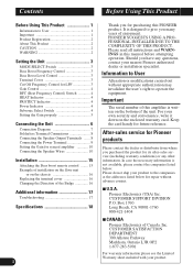
... a case, switch the power to protect all cables and important equipment such as loss or theft. 2 Receive updates on this information in damage to the RCA input of an improper fuse could result in overheating and smoke and could result. 2 Connect the battery wire directly to the car battery positive terminal (+) and the ground wire to the terminal or when changing the direction of the power supply and subwoofer. ENGLISH ESPA...
... a case, switch the power to protect all cables and important equipment such as loss or theft. 2 Receive updates on this information in damage to the RCA input of an improper fuse could result in overheating and smoke and could result. 2 Connect the battery wire directly to the car battery positive terminal (+) and the ground wire to the terminal or when changing the direction of the power supply and subwoofer. ENGLISH ESPA...
Owner's Manual
Page 4
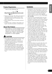
... Hz. bridge. See the "Connecting the Speaker Wires" section for LPF You can select a bass boost level from MASTER, SYNC and SYNC INV. The only time the amplifier is when amplifiers are correct. Bass Boost Level Control You can select a cut off frequency from 40 Hz to the SYNC INV mode is switched to 120 Hz with a 4 mm hexagonal wrench and remove the terminal cover. Set the MODE SELECT switch to the...
... Hz. bridge. See the "Connecting the Speaker Wires" section for LPF You can select a bass boost level from MASTER, SYNC and SYNC INV. The only time the amplifier is when amplifiers are correct. Bass Boost Level Control You can select a cut off frequency from 40 Hz to the SYNC INV mode is switched to 120 Hz with a 4 mm hexagonal wrench and remove the terminal cover. Set the MODE SELECT switch to the...
Owner's Manual
Page 5
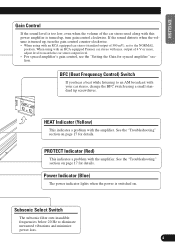
See the "Troubleshooting" section on . Power Indicator (Blue) The power indicator lights when the power is switched on page 17 for details. Subsonic Select Switch The subsonic filter cuts inaudible frequencies below 20 Hz to match the car stereo output level. • For synced amplifier's gain control, see the "Setting the Gain for details. PROTECT Indicator (Red) This indicates a problem with the amplifier. BFC (Beat Frequency Control) Switch If you hear a beat while listening to the NORMAL position. output of 4 V or more, adjust level to...
See the "Troubleshooting" section on . Power Indicator (Blue) The power indicator lights when the power is switched on page 17 for details. Subsonic Select Switch The subsonic filter cuts inaudible frequencies below 20 Hz to match the car stereo output level. • For synced amplifier's gain control, see the "Setting the Gain for details. PROTECT Indicator (Red) This indicates a problem with the amplifier. BFC (Beat Frequency Control) Switch If you hear a beat while listening to the NORMAL position. output of 4 V or more, adjust level to...
Owner's Manual
Page 6
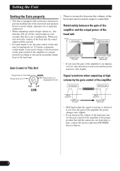
... amplifier the power changes only slightly. • If you turn down the volume of the head unit the sound output will cut , the gain control of this unit may be restored. • If sound output is equipped with a protective function to prevent malfunction of the unit itself and speakers from time to time, contact the nearest authorized PIONEER Service Station. 5 When you decrease the volume of the head unit and set the gain control of the amplifier...
... amplifier the power changes only slightly. • If you turn down the volume of the head unit the sound output will cut , the gain control of this unit may be restored. • If sound output is equipped with a protective function to prevent malfunction of the unit itself and speakers from time to time, contact the nearest authorized PIONEER Service Station. 5 When you decrease the volume of the head unit and set the gain control of the amplifier...
Owner's Manual
Page 7
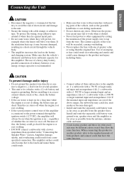
... parts. • Do not route wires where they have the same function. Turn the car stereo off when the engine is at rest or idling. • DO NOT connect a subwoofer with cable clamps or adhesive tape. regardless of the power supply wire to the product and injury including burns. Install and route the separately sold battery wire as far away as possible from the speaker wires...
... parts. • Do not route wires where they have the same function. Turn the car stereo off when the engine is at rest or idling. • DO NOT connect a subwoofer with cable clamps or adhesive tape. regardless of the power supply wire to the product and injury including burns. Install and route the separately sold battery wire as far away as possible from the speaker wires...
Owner's Manual
Page 8
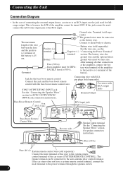
...RCA input jack Bass Boost Remote Control Wire Reverse side Speaker output terminal See the "Connecting the Speaker Wires" section for SYNC OUTPUT/SYNC INPUT jack connection instructions. The battery wire, the ground wire and the optional direct Battery ground wire must be same size. Jack for fullrange output. If the car stereo does not have a system remote control terminal, connect the male terminal to the positive (+) terminal of the battery. to the power terminal through the ignition switch. 7 Connecting wire with the bass boost remote control wire. Each amplifier...
...RCA input jack Bass Boost Remote Control Wire Reverse side Speaker output terminal See the "Connecting the Speaker Wires" section for SYNC OUTPUT/SYNC INPUT jack connection instructions. The battery wire, the ground wire and the optional direct Battery ground wire must be same size. Jack for fullrange output. If the car stereo does not have a system remote control terminal, connect the male terminal to the positive (+) terminal of the battery. to the power terminal through the ignition switch. 7 Connecting wire with the bass boost remote control wire. Each amplifier...
Owner's Manual
Page 9
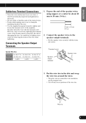
... wires. • Wrap the wire tie around the wire insulation, not the stripped wire. • Cut off any excess portions of the speaker wires using nippers or a cutter by observing the status of the amplifier. Wire tie 8 Securely fasten the wire with the terminal screws. less than 35 ft. Terminal screw Speaker output terminal Speaker wire 3. Expose the end of the wire ties. Connect the speaker wires to the speaker output terminals. • Fix the speaker wires securely with the terminal screw. Wire Size...
... wires. • Wrap the wire tie around the wire insulation, not the stripped wire. • Cut off any excess portions of the speaker wires using nippers or a cutter by observing the status of the amplifier. Wire tie 8 Securely fasten the wire with the terminal screws. less than 35 ft. Terminal screw Speaker output terminal Speaker wire 3. Expose the end of the wire ties. Connect the speaker wires to the speaker output terminals. • Fix the speaker wires securely with the terminal screw. Wire Size...
Owner's Manual
Page 10
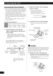
... Connecting the Unit Connecting the Power Terminal • Always use the recommended battery and ground wire, which is as follows. Wire tie 9 System remote control terminal Power terminal Battery wire Terminal screw Terminal screw GND terminal System remote control wire Ground wire WARNING Failure to securely fasten the battery wire to the terminal using nippers or a cutter. • Battery wire, ground wire: 23 mm to the car body. • Recommended wires size (AWG: American Wire Gauge) is sold separately. Connect the battery wire directly to the car battery positive terminal...
... Connecting the Unit Connecting the Power Terminal • Always use the recommended battery and ground wire, which is as follows. Wire tie 9 System remote control terminal Power terminal Battery wire Terminal screw Terminal screw GND terminal System remote control wire Ground wire WARNING Failure to securely fasten the battery wire to the terminal using nippers or a cutter. • Battery wire, ground wire: 23 mm to the car body. • Recommended wires size (AWG: American Wire Gauge) is sold separately. Connect the battery wire directly to the car battery positive terminal...
Owner's Manual
Page 11
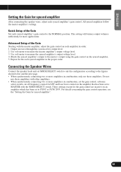
... the Gain Set each amplifier in order. 1. Connecting the Speaker Wires Connect the speaker leads and set MODE SELECT switch to suit the configuration according to the figures shown below and the next page. • When synchronously connecting two or more amplifiers in combination, set the gain control, subsonic select switch, cut off frequency control for LPF and bass boost control on the amplifier that has been set to the master's output using the gain control on the synced amplifier. 5. These settings...
... the Gain Set each amplifier in order. 1. Connecting the Speaker Wires Connect the speaker leads and set MODE SELECT switch to suit the configuration according to the figures shown below and the next page. • When synchronously connecting two or more amplifiers in combination, set the gain control, subsonic select switch, cut off frequency control for LPF and bass boost control on the amplifier that has been set to the master's output using the gain control on the synced amplifier. 5. These settings...
Owner's Manual
Page 12
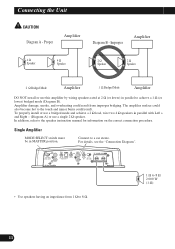
...lower) bridged mode (Diagram B). Improper Amplifier 4 Ω Speaker 4 Ω Speaker 2 Ω Speaker 2 Ω Speaker 2 Ω Bridged Mode Amplifier 1 Ω Bridged Mode Amplifier DO NOT install or use a single 2 Ω speaker. Single Amplifier MODE SELECT switch must be in parallel to the speaker instruction manual for information on the correct connection procedure. To properly install or use a bridged mode and achieve a 2 Ω load, wire two 4 Ω speakers in parallel with Left + and Right - (Diagram A) or use this amplifier by wiring speakers rated at...
...lower) bridged mode (Diagram B). Improper Amplifier 4 Ω Speaker 4 Ω Speaker 2 Ω Speaker 2 Ω Speaker 2 Ω Bridged Mode Amplifier 1 Ω Bridged Mode Amplifier DO NOT install or use a single 2 Ω speaker. Single Amplifier MODE SELECT switch must be in parallel to the speaker instruction manual for information on the correct connection procedure. To properly install or use a bridged mode and achieve a 2 Ω load, wire two 4 Ω speakers in parallel with Left + and Right - (Diagram A) or use this amplifier by wiring speakers rated at...
Owner's Manual
Page 13
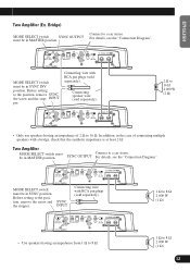
... setting to a car stereo. Two Amplifier MODE SELECT switch must be in the case of connecting multiple speakers with RCA pin plugs (sold separately). 2 Ω to 16 Ω 4 000 W (2 Ω) • Only use speakers having an impedance from 1 Ω to 8 Ω. 1 Ω to the position, remove SYNC the screw and the stop- SYNC OUTPUT For details, see the "Connection Diagram". For details, see the "Connection Diagram". ENGLISH Two Amplifier...
... setting to a car stereo. Two Amplifier MODE SELECT switch must be in the case of connecting multiple speakers with RCA pin plugs (sold separately). 2 Ω to 16 Ω 4 000 W (2 Ω) • Only use speakers having an impedance from 1 Ω to 8 Ω. 1 Ω to the position, remove SYNC the screw and the stop- SYNC OUTPUT For details, see the "Connection Diagram". For details, see the "Connection Diagram". ENGLISH Two Amplifier...
Owner's Manual
Page 14
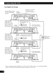
... setting to a car stereo. SYNC Connecting wire with a bridge, check that the synthetic impedance is at least 2 Ω. 13 Connecting speaker wire (sold separately). For details, see the "Connection Diagram". Connecting speaker wire (sold separately). Before setting to the position, remove the SYNC screw and the stopper. Connecting the Unit Four Amplifier (Ex. In addition, in SYNC INV position. SYNC INPUT • Only use speakers having an impedance of connecting multiple speakers with INPUT RCA pin plugs...
... setting to a car stereo. SYNC Connecting wire with a bridge, check that the synthetic impedance is at least 2 Ω. 13 Connecting speaker wire (sold separately). For details, see the "Connection Diagram". Connecting speaker wire (sold separately). Before setting to the position, remove the SYNC screw and the stopper. Connecting the Unit Four Amplifier (Ex. In addition, in SYNC INV position. SYNC INPUT • Only use speakers having an impedance of connecting multiple speakers with INPUT RCA pin plugs...
Owner's Manual
Page 15
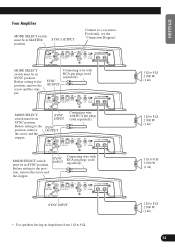
... the screw and the stopper. SYNC OUTPUT Connecting wire with RCA pin plugs (sold separately). Before setting to the position, remove the screw and the stopper. SYNC INPUT Connecting wire with RCA pin plugs (sold separately). SYNC INPUT • Use speakers having an impedance from 1 Ω to 8 Ω. 1 Ω to 8 Ω 2 000 W (1 Ω) 1 Ω to 8 Ω 2 000 W (1 Ω) 1 Ω to 8 Ω 2 000 W (1 Ω) 1 Ω to a car stereo. Connect to...
... the screw and the stopper. SYNC OUTPUT Connecting wire with RCA pin plugs (sold separately). Before setting to the position, remove the screw and the stopper. SYNC INPUT Connecting wire with RCA pin plugs (sold separately). SYNC INPUT • Use speakers having an impedance from 1 Ω to 8 Ω. 1 Ω to 8 Ω 2 000 W (1 Ω) 1 Ω to 8 Ω 2 000 W (1 Ω) 1 Ω to 8 Ω 2 000 W (1 Ω) 1 Ω to a car stereo. Connect to...
Owner's Manual
Page 16
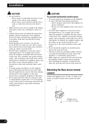
... with the driver, such as on unstable places such as the spare tire board. • The best location for example, the location where the amplifier is installed. CAUTION To prevent malfunction and/or injury • To ensure proper heat dissipation of the amplifier, be easily removed. Attaching the Bass boost remote control Attach with liquids. Use of any attached speakers could...
... with the driver, such as on unstable places such as the spare tire board. • The best location for example, the location where the amplifier is installed. CAUTION To prevent malfunction and/or injury • To ensure proper heat dissipation of the amplifier, be easily removed. Attaching the Bass boost remote control Attach with liquids. Use of any attached speakers could...
Owner's Manual
Page 17
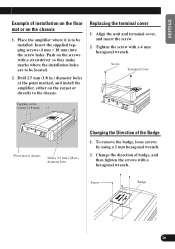
... × 18 mm) into the screw holes. Tighten the screw with a hexagonal wrench. To remove the badge, loose screws by using a 2 mm hexagonal wrench. 2. Screw Badge 16 Place the amplifier where it is to be located. 2. Drill 2.5 mm (1/8 in .) diameter hole Changing the Direction of the Badge 1. Replacing the terminal cover 1. Screw Terminal Cover Tapping screw (4 mm × 18 mm) Floor mat...
... × 18 mm) into the screw holes. Tighten the screw with a hexagonal wrench. To remove the badge, loose screws by using a 2 mm hexagonal wrench. 2. Screw Badge 16 Place the amplifier where it is to be located. 2. Drill 2.5 mm (1/8 in .) diameter hole Changing the Direction of the Badge 1. Replacing the terminal cover 1. Screw Terminal Cover Tapping screw (4 mm × 18 mm) Floor mat...
Owner's Manual
Page 18
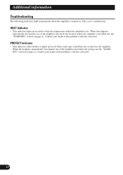
... Troubleshooting The following indicators light momentarily when the amplifier is installed (see the "WARNING" section on page 2). When this happens, immediately discontinue use of the amplifier and check the location where the amplifier is turned on page 2). HEAT Indicator • This indicator lights up in yellow when the temperature within the amplifier rises. This is not a malfunction. PROTECT Indicator • This indicator either flashes or lights up in red...
... Troubleshooting The following indicators light momentarily when the amplifier is installed (see the "WARNING" section on page 2). When this happens, immediately discontinue use of the amplifier and check the location where the amplifier is turned on page 2). HEAT Indicator • This indicator lights up in yellow when the temperature within the amplifier rises. This is not a malfunction. PROTECT Indicator • This indicator either flashes or lights up in red...
Owner's Manual
Page 19
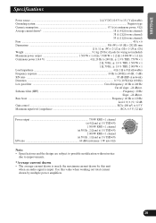
Bass boost ...Frequency: 40 Hz to 120 Hz Level: 0 / 6 / 9 / 12 dB Gain control ...RCA: 400 mV to 6.5 V Maximum input level / impedance ...RCA: 6.5 V / 22 kΩ Power output 750 W RMS × 1 channel (at 4 Ω and 1% THD+N) 1 500 W RMS × 1 channel (at 50 Hz , 2 Ω and 1% THD+N) 2 000 W RMS × 1 channel (at continuous power, 4 Ω) Average current drawn* ...18 A (4 Ω for one channel) 38 A (2 Ω for one channel) 55 A (1 Ω for one...
Bass boost ...Frequency: 40 Hz to 120 Hz Level: 0 / 6 / 9 / 12 dB Gain control ...RCA: 400 mV to 6.5 V Maximum input level / impedance ...RCA: 6.5 V / 22 kΩ Power output 750 W RMS × 1 channel (at 4 Ω and 1% THD+N) 1 500 W RMS × 1 channel (at 50 Hz , 2 Ω and 1% THD+N) 2 000 W RMS × 1 channel (at continuous power, 4 Ω) Average current drawn* ...18 A (4 Ω for one channel) 38 A (2 Ω for one channel) 55 A (1 Ω for one...

Owner's Manual
Page 56
...Chapultepec, Mexico, D.F. 11000 TEL: 55-9178-4270 Published by Pioneer Corporation. Copyright © 2007 Pioneer Corporation. de C.V. LTD. 178-184 Boundary Road, Braeside, Victoria 3195, Australia TEL: (03) 9586-6300 PIONEER ELECTRONICS OF CANADA, INC. 300 Allstate Parkway, Markham, Ontario..., Canada TEL: 1-877-283-5901 PIONEER ELECTRONICS DE MEXICO, S.A. LTD. 253 Alexandra Road, #04-01, Singapore 159936 TEL: 65-6472-7555 PIONEER ELECTRONICS AUSTRALIA PTY. Copyright © 2007 by Pioneer Corporation. Publication de Pioneer Corporation. Tous droits de reproduction et de...
...Chapultepec, Mexico, D.F. 11000 TEL: 55-9178-4270 Published by Pioneer Corporation. Copyright © 2007 Pioneer Corporation. de C.V. LTD. 178-184 Boundary Road, Braeside, Victoria 3195, Australia TEL: (03) 9586-6300 PIONEER ELECTRONICS OF CANADA, INC. 300 Allstate Parkway, Markham, Ontario..., Canada TEL: 1-877-283-5901 PIONEER ELECTRONICS DE MEXICO, S.A. LTD. 253 Alexandra Road, #04-01, Singapore 159936 TEL: 65-6472-7555 PIONEER ELECTRONICS AUSTRALIA PTY. Copyright © 2007 by Pioneer Corporation. Publication de Pioneer Corporation. Tous droits de reproduction et de...


