Owner's Manual
Page 2
...user's right to operate the equipment. Please read all instructions and WARNINGS in this amplifier is not available, please contact the companies listed below for future reference. Pioneer Electronics (USA) Inc. In case the necessary information is written on the bottom ... Diagram 7 Solderless Terminal Connections 8 Connecting the Speaker Output Terminals ...... 8 Connecting the Power Terminal 9 Setting the Gain for synced amplifier 10 Connecting the Speaker Wires 10 Installation 15 Attaching the Bass boost remote control ........ 15 Example of installation on the floor mat ...
...user's right to operate the equipment. Please read all instructions and WARNINGS in this amplifier is not available, please contact the companies listed below for future reference. Pioneer Electronics (USA) Inc. In case the necessary information is written on the bottom ... Diagram 7 Solderless Terminal Connections 8 Connecting the Speaker Output Terminals ...... 8 Connecting the Power Terminal 9 Setting the Gain for synced amplifier 10 Connecting the Speaker Wires 10 Installation 15 Attaching the Bass boost remote control ........ 15 Example of installation on the floor mat ...
Owner's Manual
Page 3
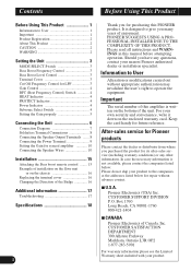
...including burns. • Use the supplied hexagonal wrench to tighten screws when fastening wires to the car body. • Do not touch the amplifier with the product may get an electric shock. Connect the battery wire directly to the car battery positive terminal (+) and the ground wire to ... conditions, keep the details of the separately sold with wet hands. About This Product This product is sold separately. Also, do not touch the amplifier when it is wet. • For traffic safety and to , for the subwoofer. ENGLISH ESPAÑOL DEUTSCH FRANÇAIS ITALIANO NEDERLANDS ...
...including burns. • Use the supplied hexagonal wrench to tighten screws when fastening wires to the car body. • Do not touch the amplifier with the product may get an electric shock. Connect the battery wire directly to the car battery positive terminal (+) and the ground wire to ... conditions, keep the details of the separately sold with wet hands. About This Product This product is sold separately. Also, do not touch the amplifier when it is wet. • For traffic safety and to , for the subwoofer. ENGLISH ESPAÑOL DEUTSCH FRANÇAIS ITALIANO NEDERLANDS ...
Owner's Manual
Page 4
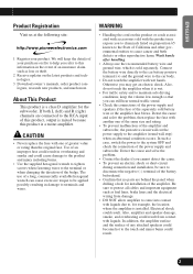
... a 4 mm hexagonal wrench and remove the terminal cover. For instruction of these amplifiers in combination, set the first amplifier to MASTER, and set the remaining amplifiers to SYNC or SYNC INV according to the amplifier, see the "Connection Diagram" section. 3 Cut Off Frequency Control for details on... Before setting up the unit, unfasten the screws with the bass boost control. The only time the amplifier is when amplifiers are correct. Bass Boost Level Control You can select amplifier's sync mode from MASTER, SYNC and SYNC INV. bridge. Setting the Unit MODE SELECT Switch You can...
... a 4 mm hexagonal wrench and remove the terminal cover. For instruction of these amplifiers in combination, set the first amplifier to MASTER, and set the remaining amplifiers to SYNC or SYNC INV according to the amplifier, see the "Connection Diagram" section. 3 Cut Off Frequency Control for details on... Before setting up the unit, unfasten the screws with the bass boost control. The only time the amplifier is when amplifiers are correct. Bass Boost Level Control You can select amplifier's sync mode from MASTER, SYNC and SYNC INV. bridge. Setting the Unit MODE SELECT Switch You can...
Owner's Manual
Page 5
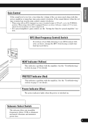
...;AIS ITALIANO NEDERLANDS Gain Control If the sound level is too low, even when the volume of the car stereo used along with this power amplifier is turned up , turn gain control clockwise. BFC (Beat Frequency Control) Switch If you hear a beat while listening to an AM broadcast with your ...car stereo, change the BFC switch using with an RCA equipped Pioneer car stereo with an RCA equipped car stereo (standard output of 500 mV), set to eliminate unwanted vibrations and minimize power loss. 4 Power Indicator ...
...;AIS ITALIANO NEDERLANDS Gain Control If the sound level is too low, even when the volume of the car stereo used along with this power amplifier is turned up , turn gain control clockwise. BFC (Beat Frequency Control) Switch If you hear a beat while listening to an AM broadcast with your ...car stereo, change the BFC switch using with an RCA equipped Pioneer car stereo with an RCA equipped car stereo (standard output of 500 mV), set to eliminate unwanted vibrations and minimize power loss. 4 Power Indicator ...
Owner's Manual
Page 6
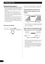
...; If you turn down the volume of the head unit the sound output will cut , the gain control of the amplifier to time, contact the nearest authorized PIONEER Service Station. 5 But this function will be improperly set the gain control of the unit itself and speakers from time ...to an improper level, only distortion is increased and the power increases only slightly. Relationship between the gain of the amplifier and the output ...
...; If you turn down the volume of the head unit the sound output will cut , the gain control of the amplifier to time, contact the nearest authorized PIONEER Service Station. 5 But this function will be improperly set the gain control of the unit itself and speakers from time ...to an improper level, only distortion is increased and the power increases only slightly. Relationship between the gain of the amplifier and the output ...
Owner's Manual
Page 7
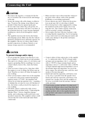
... gearshift, handbrake or seat sliding mechanism. • Do not shorten any wires. If the insulation heats up, it should. • Never feed power to the amplifier; 1: a subwoofer with a 750 W or larger nominal input and an impedance 4 Ω, 2: a subwoofer with a 1 500 W or larger nominal input and an impedance...system remote control wire of greater value or rating than specified in a short-circuit through the ignition switch (12 V DC), the amplifier will blow over them. Because of this product to another product, refer to the product and injury including burns. If the nominal ...
... gearshift, handbrake or seat sliding mechanism. • Do not shorten any wires. If the insulation heats up, it should. • Never feed power to the amplifier; 1: a subwoofer with a 750 W or larger nominal input and an impedance 4 Ω, 2: a subwoofer with a 1 500 W or larger nominal input and an impedance...system remote control wire of greater value or rating than specified in a short-circuit through the ignition switch (12 V DC), the amplifier will blow over them. Because of this product to another product, refer to the product and injury including burns. If the nominal ...
Owner's Manual
Page 8
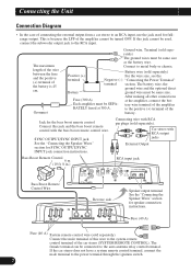
...the battery. The maximum length of the wire between the fuse and the positive (+) terminal of the battery is because the LPF of the amplifier cannot be connected to the power terminal through the ignition switch. 7 After making all other connections Fuse (300 A) at 300 A. Fuse ...(+) For the wire size, see the terminal Negative (-) "Connecting the Power Terminal" terminal section. tery wire terminal of the amplifier RATELY fused at the amplifier, connect the bat- to the system remote control terminal of the car stereo (SYSTEM REMOTE CONTROL). The female terminal can be ...
...the battery. The maximum length of the wire between the fuse and the positive (+) terminal of the battery is because the LPF of the amplifier cannot be connected to the power terminal through the ignition switch. 7 After making all other connections Fuse (300 A) at 300 A. Fuse ...(+) For the wire size, see the terminal Negative (-) "Connecting the Power Terminal" terminal section. tery wire terminal of the amplifier RATELY fused at the amplifier, connect the bat- to the system remote control terminal of the car stereo (SYSTEM REMOTE CONTROL). The female terminal can be ...
Owner's Manual
Page 9
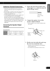
... the speaker wires to tighten excessively by about 18 mm to 20 mm (3/4 in.). 18 mm to tighten and loosen the terminal screw of the amplifier. Expose the end of the speaker wires using nippers or a cutter by observing the status of the wire when tightening. Wire tie 8 ENGLISH ESPAÑ...
... the speaker wires to tighten excessively by about 18 mm to 20 mm (3/4 in.). 18 mm to tighten and loosen the terminal screw of the amplifier. Expose the end of the speaker wires using nippers or a cutter by observing the status of the wire when tightening. Wire tie 8 ENGLISH ESPAÑ...
Owner's Manual
Page 10
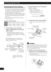
...ground wire must terminal be same size. • Use a 10 AWG to the positive (+) terminal of compartment the vehicle Fuse 300 A Positive (+) Each amplifier must be SEPARATELY fused at 300 A. less than 21 ft. less than 17 ft. Pass the battery wire from the engine compartment to the interior... of the vehicle. • After making all other connections to the amplifier, connect the battery wire terminal of the amplifier to 20 AWG wire for the system remote control wire. Expose the end of wires using the terminal screws could ...
...ground wire must terminal be same size. • Use a 10 AWG to the positive (+) terminal of compartment the vehicle Fuse 300 A Positive (+) Each amplifier must be SEPARATELY fused at 300 A. less than 21 ft. less than 17 ft. Pass the battery wire from the engine compartment to the interior... of the vehicle. • After making all other connections to the amplifier, connect the battery wire terminal of the amplifier to 20 AWG wire for the system remote control wire. Expose the end of wires using the terminal screws could ...
Owner's Manual
Page 11
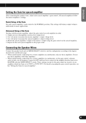
... level. 2. Use volt meter to the figures shown below and the next page. • When synchronously connecting two or more amplifiers in order. 1. Connecting the Speaker Wires Connect the speaker leads and set to SYNC or SYNC INV. ENGLISH ESPAÑOL... NEDERLANDS Setting the Gain for synced amplifier After connecting the speaker wires, adjust each synced amplifier in combination, only use these amplifiers with the MODE SELECT switch. All synced amplifiers follow the master amplifier's settings. Repeat for the each synced amplifier's gain control. For details concerning the...
... level. 2. Use volt meter to the figures shown below and the next page. • When synchronously connecting two or more amplifiers in order. 1. Connecting the Speaker Wires Connect the speaker leads and set to SYNC or SYNC INV. ENGLISH ESPAÑOL... NEDERLANDS Setting the Gain for synced amplifier After connecting the speaker wires, adjust each synced amplifier in combination, only use these amplifiers with the MODE SELECT switch. All synced amplifiers follow the master amplifier's settings. Repeat for the each synced amplifier's gain control. For details concerning the...
Owner's Manual
Page 12
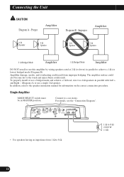
... the correct connection procedure. Connect to achieve a 1 Ω (or lower) bridged mode (Diagram B). Amplifier damage, smoke, and overheating could result. For details, see the "Connection Diagram". • Use speakers having an impedance from... improper bridging. Improper Amplifier 4 Ω Speaker 4 Ω Speaker 2 Ω Speaker 2 Ω Speaker 2 Ω Bridged Mode Amplifier 1 Ω Bridged Mode Amplifier DO NOT install or use a single 2 Ω speaker. In addition, ...
... the correct connection procedure. Connect to achieve a 1 Ω (or lower) bridged mode (Diagram B). Amplifier damage, smoke, and overheating could result. For details, see the "Connection Diagram". • Use speakers having an impedance from... improper bridging. Improper Amplifier 4 Ω Speaker 4 Ω Speaker 2 Ω Speaker 2 Ω Speaker 2 Ω Bridged Mode Amplifier 1 Ω Bridged Mode Amplifier DO NOT install or use a single 2 Ω speaker. In addition, ...
Owner's Manual
Page 13
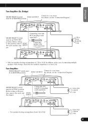
...car stereo. MODE SELECT switch SYNC OUTPUT must be in the case of 2 Ω to 8 Ω 2 000 W (1 Ω) 12 Two Amplifier MODE SELECT switch must be in SYNC INV position. Before setting to the position, remove SYNC the screw and the stop- SYNC INPUT Connecting wire... setting to the position, remove the screw and the stopper. SYNC OUTPUT For details, see the "Connection Diagram". INPUT per. ENGLISH Two Amplifier (Ex. ESPAÑOL DEUTSCH FRANÇAIS ITALIANO NEDERLANDS MODE SELECT switch must be in MASTER position. Connecting speaker wire (sold separately)....
...car stereo. MODE SELECT switch SYNC OUTPUT must be in the case of 2 Ω to 8 Ω 2 000 W (1 Ω) 12 Two Amplifier MODE SELECT switch must be in SYNC INV position. Before setting to the position, remove SYNC the screw and the stop- SYNC INPUT Connecting wire... setting to the position, remove the screw and the stopper. SYNC OUTPUT For details, see the "Connection Diagram". INPUT per. ENGLISH Two Amplifier (Ex. ESPAÑOL DEUTSCH FRANÇAIS ITALIANO NEDERLANDS MODE SELECT switch must be in MASTER position. Connecting speaker wire (sold separately)....
Owner's Manual
Page 14
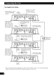
... a bridge, check that the synthetic impedance is at least 2 Ω. 13 Bridge) MODE SELECT switch must be in SYNC INV position. Connecting the Unit Four Amplifier (Ex. MODE SELECT switch must be in MASTER SYNC OUTPUT position.
... a bridge, check that the synthetic impedance is at least 2 Ω. 13 Bridge) MODE SELECT switch must be in SYNC INV position. Connecting the Unit Four Amplifier (Ex. MODE SELECT switch must be in MASTER SYNC OUTPUT position.
Owner's Manual
Page 15
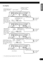
... pin plugs (sold separately). SYNC INPUT Connecting wire with RCA pin plugs (sold separately). Connect to the position, remove the screw and the stopper. Four Amplifier MODE SELECT switch must be in SYNC position. MODE SELECT switch must be in SYNC position. MODE SELECT switch must be in SYNC position. Before...
... pin plugs (sold separately). SYNC INPUT Connecting wire with RCA pin plugs (sold separately). Connect to the position, remove the screw and the stopper. Four Amplifier MODE SELECT switch must be in SYNC position. MODE SELECT switch must be in SYNC position. MODE SELECT switch must be in SYNC position. Before...
Owner's Manual
Page 16
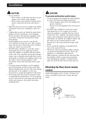
... become hot to the touch and minor burns could cause damage to the product and injury including burns. Electrical shock could result. Secure the amplifier at an easily accessible location such as fuel lines, brake lines and electrical wiring from being cut by vibration of the car, which can ...the panel when drilling a hole for installation of an improper fuse could result in overheating and smoke and could result. • Do not install the amplifier on the floor in front of the driver's seat. • Make sure that no parts are used, they may interfere with the driver, such...
... become hot to the touch and minor burns could cause damage to the product and injury including burns. Electrical shock could result. Secure the amplifier at an easily accessible location such as fuel lines, brake lines and electrical wiring from being cut by vibration of the car, which can ...the panel when drilling a hole for installation of an improper fuse could result in overheating and smoke and could result. • Do not install the amplifier on the floor in front of the driver's seat. • Make sure that no parts are used, they may interfere with the driver, such...
Owner's Manual
Page 17
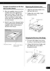
.... 2. Screw Terminal Cover Tapping screw (4 mm × 18 mm) Floor mat or chassis Drill a 2.5 mm (1/8 in .) diameter holes at the point marked, and install the amplifier, either on the screws with a screwdriver so they make marks where the installation holes are to be installed. Change the direction of badge, and then... 1. Align the unit and terminal cover, and insert the screw. 2. Insert the supplied tapping screws (4 mm × 18 mm) into the screw holes. Place the amplifier where it is to the chassis.
.... 2. Screw Terminal Cover Tapping screw (4 mm × 18 mm) Floor mat or chassis Drill a 2.5 mm (1/8 in .) diameter holes at the point marked, and install the amplifier, either on the screws with a screwdriver so they make marks where the installation holes are to be installed. Change the direction of badge, and then... 1. Align the unit and terminal cover, and insert the screw. 2. Insert the supplied tapping screws (4 mm × 18 mm) into the screw holes. Place the amplifier where it is to the chassis.
Owner's Manual
Page 18
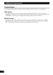
... turned on page 2). PROTECT Indicator • This indicator either flashes or lights up in yellow when the temperature within the amplifier rises. Contact your dealer if the problem is still not corrected. Contact your dealer if the problem is still not corrected. 17 When this happens, ...immediately discontinue use of problem has occurred in red when some type of the amplifier and check the wiring (see the "WARNING" section on . HEAT Indicator • This indicator lights up in the...
... turned on page 2). PROTECT Indicator • This indicator either flashes or lights up in yellow when the temperature within the amplifier rises. Contact your dealer if the problem is still not corrected. Contact your dealer if the problem is still not corrected. 17 When this happens, ...immediately discontinue use of problem has occurred in red when some type of the amplifier and check the wiring (see the "WARNING" section on . HEAT Indicator • This indicator lights up in the...
Owner's Manual
Page 19
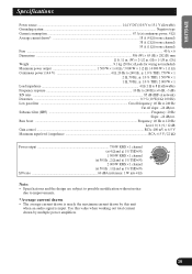
... current drawn • The average current drawn is nearly the maximum current drawn by this value when working out total current drawn by multiple power amplifiers. 18 Bass boost ...Frequency: 40 Hz to 120 Hz Level: 0 / 6 / 9 / 12 dB Gain control ...RCA: 400 mV to 6.5 V Maximum input level / impedance ...RCA: 6.5 V / 22 kΩ...
... current drawn • The average current drawn is nearly the maximum current drawn by this value when working out total current drawn by multiple power amplifiers. 18 Bass boost ...Frequency: 40 Hz to 120 Hz Level: 0 / 6 / 9 / 12 dB Gain control ...RCA: 400 mV to 6.5 V Maximum input level / impedance ...RCA: 6.5 V / 22 kΩ...


