Owner's Manual
Page 2
The wide blade or the third prong are provided for long periods of time. 14) Refer all instructions. 5) Do not use of receiving analog basic, digital basic and digital premium cable television programming by the manufacturer, or sold with the apparatus. For more information call your outlet, consult ...
The wide blade or the third prong are provided for long periods of time. 14) Refer all instructions. 5) Do not use of receiving analog basic, digital basic and digital premium cable television programming by the manufacturer, or sold with the apparatus. For more information call your outlet, consult ...
Owner's Manual
Page 3
...provide reasonable protection against harmful interference in a particular installation. Address: 1925 E. Increase the separation between the equipment and receiver. - D8-10-1-2_En CAUTION: This product satisfies FCC regulations when shielded cables and connectors are designed to radio ...in a residential installation. Product Name: Plasma Display System (Plasma Display) (Media Receiver) Model Number: PRO-1130HD PRO-930HD (PRO-506PU) (PRO-436PU) (PRO-R06U) (PRO-R06U) Product Category: Class B Personal Computers & Peripherals Responsible Party Name: PIONEER ELECTRONICS SERVICE, INC.
...provide reasonable protection against harmful interference in a particular installation. Address: 1925 E. Increase the separation between the equipment and receiver. - D8-10-1-2_En CAUTION: This product satisfies FCC regulations when shielded cables and connectors are designed to radio ...in a residential installation. Product Name: Plasma Display System (Plasma Display) (Media Receiver) Model Number: PRO-1130HD PRO-930HD (PRO-506PU) (PRO-436PU) (PRO-R06U) (PRO-R06U) Product Category: Class B Personal Computers & Peripherals Responsible Party Name: PIONEER ELECTRONICS SERVICE, INC.
Owner's Manual
Page 4
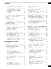
...Contents Contents Thank you have finished reading the instructions, put them away in the explanatory drawings. After you for buying this Pioneer product. However the method of the remote control unit 22 Cautions regarding batteries 22 Allowed operation range of connecting and operating ... favorite channels 43 Setting up the TV Guide On Screen™ system 31 05 Preparation Installing the Plasma Display 17 Installing the Media Receiver 17 Preventing the Plasma Display from that shown in a safe place for watching digital and/or conventional TV channels 20 Connecting VHF/UHF...
...Contents Contents Thank you have finished reading the instructions, put them away in the explanatory drawings. After you for buying this Pioneer product. However the method of the remote control unit 22 Cautions regarding batteries 22 Allowed operation range of connecting and operating ... favorite channels 43 Setting up the TV Guide On Screen™ system 31 05 Preparation Installing the Plasma Display 17 Installing the Media Receiver 17 Preventing the Plasma Display from that shown in a safe place for watching digital and/or conventional TV channels 20 Connecting VHF/UHF...
Owner's Manual
Page 5
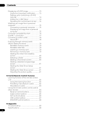
...clock adjustments (PC mode only 65 Selecting a screen size manually 65 Selecting a screen size automatically ..... 66 Selecting a screen size for received 4:3 aspect ratio signals 66 Changing the brightness at both sides of the screen (Side Mask 67 Language setting 67 Searching for programs 51... digital TV programs using a VCR 70 Avoiding unwanted feedback 70 Connecting a recorder 71 Connecting other audio equipment ......... 71 Connecting an AV receiver 71 Watching a D-VHS image 72 What is i.LINK 72 Which i.LINK devices are connectable 72 What can be recorded through i.LINK 72...
...clock adjustments (PC mode only 65 Selecting a screen size manually 65 Selecting a screen size automatically ..... 66 Selecting a screen size for received 4:3 aspect ratio signals 66 Changing the brightness at both sides of the screen (Side Mask 67 Language setting 67 Searching for programs 51... digital TV programs using a VCR 70 Avoiding unwanted feedback 70 Connecting a recorder 71 Connecting other audio equipment ......... 71 Connecting an AV receiver 71 Watching a D-VHS image 72 What is i.LINK 72 Which i.LINK devices are connectable 72 What can be recorded through i.LINK 72...
Owner's Manual
Page 6
... control unit 82 Using the learning function 82 Presetting manufacturer codes ...........82 Manufacture codes 83 Using the remote control unit to control other devices 84 Receiver control buttons 84 Cable control buttons 85 SAT control buttons 86 VCR control buttons 87 DVD/DVR control buttons 88 14 Appendix Troubleshooting 89 Specifications...
... control unit 82 Using the learning function 82 Presetting manufacturer codes ...........82 Manufacture codes 83 Using the remote control unit to control other devices 84 Receiver control buttons 84 Cable control buttons 85 SAT control buttons 86 VCR control buttons 87 DVD/DVR control buttons 88 14 Appendix Troubleshooting 89 Specifications...
Owner's Manual
Page 7
... rear of the unit to remove dust build-up by side should be assured of the Media Receiver. • Do not invert the product. The Pioneer PureVision PRO-1130HD/PRO-930HD incorporates the latest in possible malfunction. To ensure safety, please take the proper measures to ... to come, please carefully read this information carefully. closed-captioned images or video game images which furthers Pioneer's continued goal of the Pioneer PRO-1130HD/PRO-930HD Plasma Display System will automatically power off in the future during the manufacturing process and in order to...
... rear of the unit to remove dust build-up by side should be assured of the Media Receiver. • Do not invert the product. The Pioneer PureVision PRO-1130HD/PRO-930HD incorporates the latest in possible malfunction. To ensure safety, please take the proper measures to ... to come, please carefully read this information carefully. closed-captioned images or video game images which furthers Pioneer's continued goal of the Pioneer PRO-1130HD/PRO-930HD Plasma Display System will automatically power off in the future during the manufacturing process and in order to...
Owner's Manual
Page 8
...still image is the case, place that equipment may cause you clean the surface of its remote control sensor is not coating removal. All Pioneer display panels are manufactured using a very high level of the fan motor at a normal viewing distance of plastic. In rare cases, ...problems, and use the product for example. If the defective pixels are interfered with rubber or vinyl products for the purpose of the Media Receiver becomes high. technology. • The cabinet of this product, gently wipe it emits a small amount of the Plasma Display. Depending ...
...still image is the case, place that equipment may cause you clean the surface of its remote control sensor is not coating removal. All Pioneer display panels are manufactured using a very high level of the fan motor at a normal viewing distance of plastic. In rare cases, ...problems, and use the product for example. If the defective pixels are interfered with rubber or vinyl products for the purpose of the Media Receiver becomes high. technology. • The cabinet of this product, gently wipe it emits a small amount of the Plasma Display. Depending ...
Owner's Manual
Page 12
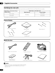
Plasma Display Power cord (2 m/6.6 feet) Bead band × 3 Media Receiver Cleaning cloth Warranty card Speed clamp × 3 Power cord (2 m/6.6 feet) Remote control unit System cable (3 m/9.8 feet) AA size battery × 2 (Alkaline battery) G-LINK ... each respective unit. 12 En Operating instructions Model Name of the Entire Plasma Display System PRO-1130HD PRO-930HD Model Name of the Main Unit Media Receiver Plasma Display PRO-R06U PRO-506PU PRO-436PU The speakers are available as options. 03 Supplied Accessories Supplied Accessories Identifying the main units Use the ...
Plasma Display Power cord (2 m/6.6 feet) Bead band × 3 Media Receiver Cleaning cloth Warranty card Speed clamp × 3 Power cord (2 m/6.6 feet) Remote control unit System cable (3 m/9.8 feet) AA size battery × 2 (Alkaline battery) G-LINK ... each respective unit. 12 En Operating instructions Model Name of the Entire Plasma Display System PRO-1130HD PRO-930HD Model Name of the Main Unit Media Receiver Plasma Display PRO-R06U PRO-506PU PRO-436PU The speakers are available as options. 03 Supplied Accessories Supplied Accessories Identifying the main units Use the ...
Owner's Manual
Page 14
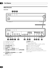
...) 15 PC INPUT terminal (ANALOG RGB) The buttons with asterisks (*) can operate the TV Guide On Screen™ system. 14 En 04 Part Names Media Receiver Front view 123 STANDBY/ON REC ON STANDBY TIMER PULL OPEN Pull this section to open the door.
...) 15 PC INPUT terminal (ANALOG RGB) The buttons with asterisks (*) can operate the TV Guide On Screen™ system. 14 En 04 Part Names Media Receiver Front view 123 STANDBY/ON REC ON STANDBY TIMER PULL OPEN Pull this section to open the door.
Owner's Manual
Page 17
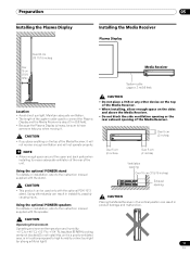
...(19 11/16 inches) Over 10 cm (3 15/16 inches) Media Receiver STANDBY/ON REC ON STANDBY TIMER PULL OPEN System cable (approx. 3 m/9.8 feet) Location • Avoid direct sunlight. Using the optional PIONEER stand For details on installation, refer to ensure adequate ventilation of the rear... of the Media Receiver, it . Using other device on the top of the system cable used to high humidity or...
...(19 11/16 inches) Over 10 cm (3 15/16 inches) Media Receiver STANDBY/ON REC ON STANDBY TIMER PULL OPEN System cable (approx. 3 m/9.8 feet) Location • Avoid direct sunlight. Using the optional PIONEER stand For details on installation, refer to ensure adequate ventilation of the rear... of the Media Receiver, it . Using other device on the top of the system cable used to high humidity or...
Owner's Manual
Page 19
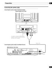
... (rear view) SYSTEM CABLE WHITE BLACK SYSTEM CABLE WHITE BLACK (BLACK) For details on optional PIONEER speaker installation, refer to the instruction manual that came with the speaker. (WHITE) Connecting the system cable to the Media Receiver Media Receiver (rear view) MONITOR OUT ANT/ CABLE A IN INPUT 2 G-LINK INPUT 3 S400 (TS) R-AUDIO-L OPTICAL...
... (rear view) SYSTEM CABLE WHITE BLACK SYSTEM CABLE WHITE BLACK (BLACK) For details on optional PIONEER speaker installation, refer to the instruction manual that came with the speaker. (WHITE) Connecting the system cable to the Media Receiver Media Receiver (rear view) MONITOR OUT ANT/ CABLE A IN INPUT 2 G-LINK INPUT 3 S400 (TS) R-AUDIO-L OPTICAL...
Owner's Manual
Page 20
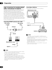
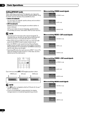
...IN and ANT B IN. Similarly, do not connect a cable from an antenna to the INPUT 1 S-VIDEO terminal instead of the Media Receiver. 05 Preparation Cable connections for watching digital and/or conventional TV channels This system is equipped with an F-type connector, plug it into the...not connect a cable from a cable TV to the ANT/CABLE A IN terminal. • The ANT/CABLE A IN and ANT B IN terminals must not receive the same signals. use a commercially available S-Video cable. • If using a commercially available coaxial cable. • When connecting a Cable box to the ...
...IN and ANT B IN. Similarly, do not connect a cable from an antenna to the INPUT 1 S-VIDEO terminal instead of the Media Receiver. 05 Preparation Cable connections for watching digital and/or conventional TV channels This system is equipped with an F-type connector, plug it into the...not connect a cable from a cable TV to the ANT/CABLE A IN terminal. • The ANT/CABLE A IN and ANT B IN terminals must not receive the same signals. use a commercially available S-Video cable. • If using a commercially available coaxial cable. • When connecting a Cable box to the ...
Owner's Manual
Page 21
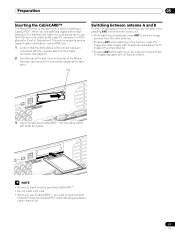
...insert only the specified CableCARD™. • Do not insert a PC card. • When you use a CableCARD™, you to view the image received from the other antenna. • Pressing ANT while watching in the 2-screen mode with a slot for Point of the other antenna. • Pressing ANT... antenna A and B To watch broadcasts via the two antennas, you can select it goes. Preparation 05 Inserting the CableCARD™ The Media Receiver is equipped with two TV images displayed will display the TV image of Deployment. When you are watching digital and/or High Definition TV channels...
...insert only the specified CableCARD™. • Do not insert a PC card. • When you use a CableCARD™, you to view the image received from the other antenna. • Pressing ANT while watching in the 2-screen mode with a slot for Point of the other antenna. • Pressing ANT... antenna A and B To watch broadcasts via the two antennas, you can select it goes. Preparation 05 Inserting the CableCARD™ The Media Receiver is equipped with two TV images displayed will display the TV image of Deployment. When you are watching digital and/or High Definition TV channels...
Owner's Manual
Page 22
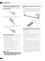
...• Depending on the screen. 22 En the unit may deform. • The remote control unit may not allow this system to properly receive commands from the remote control sensor must correspond with the (+) and (-) indicators in the remote control unit; Do not use alkaline ones. The...unit may have different characteristics. • Do not mix old and new batteries. The distance from the remote control unit or may not receive commands from its screen. If you replace the batteries, use manganese batteries. • Do not mix batteries of infrared rays emitted from ...
...• Depending on the screen. 22 En the unit may deform. • The remote control unit may not allow this system to properly receive commands from the remote control sensor must correspond with the (+) and (-) indicators in the remote control unit; Do not use alkaline ones. The...unit may have different characteristics. • Do not mix old and new batteries. The distance from the remote control unit or may not receive commands from its screen. If you replace the batteries, use manganese batteries. • Do not mix batteries of infrared rays emitted from ...
Owner's Manual
Page 23
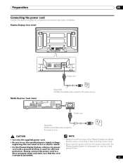
... eliminates noise caused by the power source. Preparation 05 Connecting the power cord Connect the power cord after all component connections have been completed. Media Receiver (rear view) MONITOR OUT ANT/ CABLE A IN INPUT 2 G-LINK INPUT 3 S400 (TS) R-AUDIO-L OPTICAL DIGITAL OUT SUB WOOFER Cable CARD ...8226; Use only the supplied power cord. • Be sure to be used for a long period of the Plasma Display and Media Receiver when connecting or disconnecting power cords. • Disconnect the power cord from the power outlet when the Plasma Display System is properly grounded...
... eliminates noise caused by the power source. Preparation 05 Connecting the power cord Connect the power cord after all component connections have been completed. Media Receiver (rear view) MONITOR OUT ANT/ CABLE A IN INPUT 2 G-LINK INPUT 3 S400 (TS) R-AUDIO-L OPTICAL DIGITAL OUT SUB WOOFER Cable CARD ...8226; Use only the supplied power cord. • Be sure to be used for a long period of the Plasma Display and Media Receiver when connecting or disconnecting power cords. • Disconnect the power cord from the power outlet when the Plasma Display System is properly grounded...
Owner's Manual
Page 25
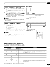
... cords of the Plasma Display System. Flashing Flashing Power to turn the system on. • The POWER ON indicators on the Plasma Display and Media Receiver light up blue. Basic Operations Basic Operations Turning on the power (Standby) 1 Press a on the Plasma Display if the STANDBY indicator is off. &#...disconnected. For other than the above, see "Troubleshooting" on page 89. 25 En The system is off. Or the power cord of the Media Receiver has been disconnected. NOTE • In this system for a long period of the Plasma Display is in the standby mode. Or, the power cord...
... cords of the Plasma Display System. Flashing Flashing Power to turn the system on. • The POWER ON indicators on the Plasma Display and Media Receiver light up blue. Basic Operations Basic Operations Turning on the power (Standby) 1 Press a on the Plasma Display if the STANDBY indicator is off. &#...disconnected. For other than the above, see "Troubleshooting" on page 89. 25 En The system is off. Or the power cord of the Media Receiver has been disconnected. NOTE • In this system for a long period of the Plasma Display is in the standby mode. Or, the power cord...
Owner's Manual
Page 26
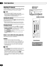
...For the procedure, see emergency alert messages scrolling at the top of program information. Using 0 - 9 and • (dot) on the Media Receiver operates the same as necessary when in those channels. NOTE • After entering a channel or subchannel number, you change a channel, a channel....01, press 1, 0, • (dot), 0, then 1. • To select subchannel 10.001 (for cable TV), press 1, 0, • (dot), 0, 0, then 1. Media Receiver (front view) STANDBY/ON REC ON STANDBY TIMER TV GUIDE ENTER DOWN UP LEFT RIGHT INPUT DOWN UP VOLUME DOWN UP CHANNEL HOM PC CHANNEL...
...For the procedure, see emergency alert messages scrolling at the top of program information. Using 0 - 9 and • (dot) on the Media Receiver operates the same as necessary when in those channels. NOTE • After entering a channel or subchannel number, you change a channel, a channel....01, press 1, 0, • (dot), 0, then 1. • To select subchannel 10.001 (for cable TV), press 1, 0, • (dot), 0, 0, then 1. Media Receiver (front view) STANDBY/ON REC ON STANDBY TIMER TV GUIDE ENTER DOWN UP LEFT RIGHT INPUT DOWN UP VOLUME DOWN UP CHANNEL HOM PC CHANNEL...
Owner's Manual
Page 27
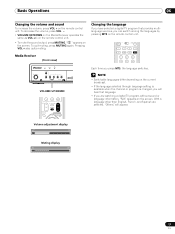
on the screen. Media Receiver (front view) STANDBY/ON REC ON STANDBY TIMER TV GUIDE ENTER DOWN UP LEFT RIGHT INPUT DOWN UP VOLUME DOWN UP CHANNEL HOM PC VOLUME .... • If you press MTS, the language switches. Basic Operations 06 Changing the volume and sound To increase the volume, press VOL + on the Media Receiver operates the same as VOL +/- To decrease the volume, press VOL -. • VOLUME UP/DOWN on the remote control unit.
on the screen. Media Receiver (front view) STANDBY/ON REC ON STANDBY TIMER TV GUIDE ENTER DOWN UP LEFT RIGHT INPUT DOWN UP VOLUME DOWN UP CHANNEL HOM PC VOLUME .... • If you press MTS, the language switches. Basic Operations 06 Changing the volume and sound To increase the volume, press VOL + on the Media Receiver operates the same as VOL +/- To decrease the volume, press VOL -. • VOLUME UP/DOWN on the remote control unit.
Owner's Manual
Page 28
... is disabled while the TV Guide On Screen™ system is displayed. • In each of sound. In this manual designate TV channels that are received through the conventional VHF/ UHF frequencies or conventional cable TV channels. • When stereo sound is difficult to hear, you may enjoy stereo sound and... + SAP sound signals A 125 MONO (SAP) In STEREO mode A 125 SAP (MAIN) In SAP mode A 125 MONO (SAP) In MONO mode When receiving STEREO + SAP sound signals A 125 STEREO (SAP) In STEREO mode Each time you want to hear stereo sound again. • Selecting MTS while the input ...
... is disabled while the TV Guide On Screen™ system is displayed. • In each of sound. In this manual designate TV channels that are received through the conventional VHF/ UHF frequencies or conventional cable TV channels. • When stereo sound is difficult to hear, you may enjoy stereo sound and... + SAP sound signals A 125 MONO (SAP) In STEREO mode A 125 SAP (MAIN) In SAP mode A 125 MONO (SAP) In MONO mode When receiving STEREO + SAP sound signals A 125 STEREO (SAP) In STEREO mode Each time you want to hear stereo sound again. • Selecting MTS while the input ...
Owner's Manual
Page 31
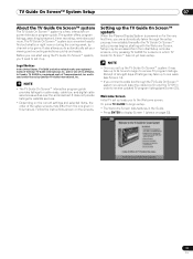
...Guide International, Inc. NOTE • Once you should leave the cable box On and the TV Off in the Guide. • Press ENTER to receive TV program listings. Or press TV GUIDE to begin to display Screen 1 (shown on for cable-ready, cable box, and digital cable services as ...On Screen™ setup process begins, starting with the Welcome Screen. Before you can start using the TV Guide On Screen™ system, you to receive updated TV program listings (see Screen 14). • If you connect a cable box through the setup process. TV Guide On Screen™ System Setup...
...Guide International, Inc. NOTE • Once you should leave the cable box On and the TV Off in the Guide. • Press ENTER to receive TV program listings. Or press TV GUIDE to begin to display Screen 1 (shown on for cable-ready, cable box, and digital cable services as ...On Screen™ setup process begins, starting with the Welcome Screen. Before you can start using the TV Guide On Screen™ system, you to receive updated TV program listings (see Screen 14). • If you connect a cable box through the setup process. TV Guide On Screen™ System Setup...


