

Owner's Manual
Page 8
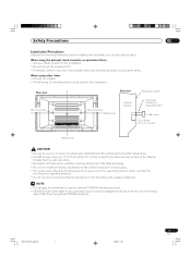
.... b. c. When the product does not operate properly as the original parts. Use of your product, please read and understood before installing the speakers. Do not cover or block these vents and openings since they can result in fire, electric shock and/or other heat- En PDP-ELITE-...in fire or personal injury. f. broken, resulting in discoloration or warp. 11. The Plasma Display weighs about 38 kg (83.8 lbs.) for the PRO-504PU and about 30.5 kg (67.3 lbs.) for future reference. 3. properly to direct sunlight for built-in installation; This product has been engineered and...
.... b. c. When the product does not operate properly as the original parts. Use of your product, please read and understood before installing the speakers. Do not cover or block these vents and openings since they can result in fire, electric shock and/or other heat- En PDP-ELITE-...in fire or personal injury. f. broken, resulting in discoloration or warp. 11. The Plasma Display weighs about 38 kg (83.8 lbs.) for the PRO-504PU and about 30.5 kg (67.3 lbs.) for future reference. 3. properly to direct sunlight for built-in installation; This product has been engineered and...
Owner's Manual
Page 9
...bolts. • For details, see the instruction manual that comes with any personal injury or product damage that results from the stand, with speakers attached. • It is strongly recommended to use of mounting items other than the above . • Be careful not to block .... When using other items • Consult your dealer to perform the installation. • Be sure to use the optional PIONEER mounting products. • PIONEER shall not be used for the installation: Rear view Mounting hole Side view Mounting surface Mounting hole Median line Plasma Display Mounting...
...bolts. • For details, see the instruction manual that comes with any personal injury or product damage that results from the stand, with speakers attached. • It is strongly recommended to use of mounting items other than the above . • Be careful not to block .... When using other items • Consult your dealer to perform the installation. • Be sure to use the optional PIONEER mounting products. • PIONEER shall not be used for the installation: Rear view Mounting hole Side view Mounting surface Mounting hole Median line Plasma Display Mounting...

Owner's Manual
Page 12
05 Supplied Accessories Plasma Display Power cord (2 m/6.6 feet) Cleaning cloth Speed clamp x 3 Bead band x 3 Media Receiver Warranty card Speaker cushion x 3 (Use when installing the optional speakers at the bottom of the Plasma Display.) Power cord (2 m/6.6 feet) Remote control unit System cable (3 m/9.8 feet) AA size battery x 2 (Alkaline battery) Stand Screw x 4 (for stand) ...
05 Supplied Accessories Plasma Display Power cord (2 m/6.6 feet) Cleaning cloth Speed clamp x 3 Bead band x 3 Media Receiver Warranty card Speaker cushion x 3 (Use when installing the optional speakers at the bottom of the Plasma Display.) Power cord (2 m/6.6 feet) Remote control unit System cable (3 m/9.8 feet) AA size battery x 2 (Alkaline battery) Stand Screw x 4 (for stand) ...

Owner's Manual
Page 13
buttons Rear view 9 - 0 = 9 SYSTEM CABLE terminal (BLACK) 0 SYSTEM CABLE terminal (WHITE) The terminals have faced downward. - SPEAKER (right/left) terminals = AC INLET terminal PDP-ELITE-Eng (13-16) 13 13 En 9/9/03, 11:43 buttons 8 CHANNEL +/- Part Names Plasma Display Front view 06 (right view) 5 6 7 8 2 1 3 1 POWER button 2 STANDBY indicator 3 POWER ON indicator 4 Remote control sensor 4 5 STANDBY/ON button 6 INPUT button 7 VOLUME +/-
buttons Rear view 9 - 0 = 9 SYSTEM CABLE terminal (BLACK) 0 SYSTEM CABLE terminal (WHITE) The terminals have faced downward. - SPEAKER (right/left) terminals = AC INLET terminal PDP-ELITE-Eng (13-16) 13 13 En 9/9/03, 11:43 buttons 8 CHANNEL +/- Part Names Plasma Display Front view 06 (right view) 5 6 7 8 2 1 3 1 POWER button 2 STANDBY indicator 3 POWER ON indicator 4 Remote control sensor 4 5 STANDBY/ON button 6 INPUT button 7 VOLUME +/-

Owner's Manual
Page 17
...276 inches) and the angle relative to the sensor must be within 30 degrees in instability causing possible injury. Using the optional PIONEER speakers • For details on installation, refer to the instruction manual provided with new ones early enough. Operating Environment Operating environment temperature...remote control sensor (t) located at the following locations: • Under direct exposure to +104°F); Using the optional PIONEER stand • For details on installation, refer to the instruction manual provided with other stands may not receive commands from...
...276 inches) and the angle relative to the sensor must be within 30 degrees in instability causing possible injury. Using the optional PIONEER speakers • For details on installation, refer to the instruction manual provided with new ones early enough. Operating Environment Operating environment temperature...remote control sensor (t) located at the following locations: • Under direct exposure to +104°F); Using the optional PIONEER stand • For details on installation, refer to the instruction manual provided with other stands may not receive commands from...

Owner's Manual
Page 20
..., 11:44 07 Preparation Setting the system Connecting the system cable to the Plasma Display Plasma Display (rear view) (WHITE) (BLACK) For details on optional PIONEER speaker installation, refer to the Media Receiver Media Receiver (rear view) SERVICE ONLY IN OUT CONTROL VCR CONTROL IN OUT IN OUT S-VIDEO DIGITAL OUT OPTICAL.../PR A ANTENNA/CABLE B MONITOR OUT S-VIDEO VIDEO R-AUDIO-L S-VIDEO R-AUDIO-L INPUT 3 Y CB/PB CR/PR AC INLET BLACK WHITE SYSTEM CABLE (BLACK) (WHITE) • THESE SPEAKER TERMINALS CAN BE UNDER HAZARDOUS VOLTAGE WHEN YOU CONNECT OR DISCONNECT THE...
..., 11:44 07 Preparation Setting the system Connecting the system cable to the Plasma Display Plasma Display (rear view) (WHITE) (BLACK) For details on optional PIONEER speaker installation, refer to the Media Receiver Media Receiver (rear view) SERVICE ONLY IN OUT CONTROL VCR CONTROL IN OUT IN OUT S-VIDEO DIGITAL OUT OPTICAL.../PR A ANTENNA/CABLE B MONITOR OUT S-VIDEO VIDEO R-AUDIO-L S-VIDEO R-AUDIO-L INPUT 3 Y CB/PB CR/PR AC INLET BLACK WHITE SYSTEM CABLE (BLACK) (WHITE) • THESE SPEAKER TERMINALS CAN BE UNDER HAZARDOUS VOLTAGE WHEN YOU CONNECT OR DISCONNECT THE...

Owner's Manual
Page 21
... system cables together so that time be difficult to undo once in place. Please attach them carefully. When the speakers are included with this system for bunching cables. Use pliers to twist the clamp 90°, pulling outward. Once properly bunched, follow the steps ...to lock the clamp. Preparation 07 Routing cables Speed clamps and bead bands are installed on the sides (rear view) Speaker cable Cable binders (supplied Speed clamps with the stand)* Speaker cable Attaching speed clamps to the main unit Attach the speed clamps using the 4 holes marked with below to route the...
... system cables together so that time be difficult to undo once in place. Please attach them carefully. When the speakers are included with this system for bunching cables. Use pliers to twist the clamp 90°, pulling outward. Once properly bunched, follow the steps ...to lock the clamp. Preparation 07 Routing cables Speed clamps and bead bands are installed on the sides (rear view) Speaker cable Cable binders (supplied Speed clamps with the stand)* Speaker cable Attaching speed clamps to the main unit Attach the speed clamps using the 4 holes marked with below to route the...

Owner's Manual
Page 38
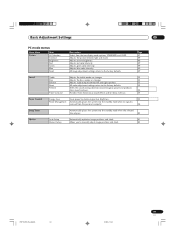
... Settings Using the menu AV mode menus Home Menu Picture Item AV Selection Contrast Brightness Color Tint Sharpness Pro Adjust Reset Description Select from changing especially Parental Control settings. Adjusts the picture between left and right speakers. 53 All audio adjustment settings return to be used for on the remote control unit.
... Settings Using the menu AV mode menus Home Menu Picture Item AV Selection Contrast Brightness Color Tint Sharpness Pro Adjust Reset Description Select from changing especially Parental Control settings. Adjusts the picture between left and right speakers. 53 All audio adjustment settings return to be used for on the remote control unit.
Owner's Manual
Page 39
... optimizes image positions and clock. 81 Manual Setup Allows you to the factory defaults. Adjusts green color intensity. Adjusts the picture between left and right speakers. 53 All audio adjustment settings return to the factory defaults. 53 Shifts the sound coming direction (sound images) upward and produces clear sound contours. 54...
... optimizes image positions and clock. 81 Manual Setup Allows you to the factory defaults. Adjusts green color intensity. Adjusts the picture between left and right speakers. 53 All audio adjustment settings return to the factory defaults. 53 Shifts the sound coming direction (sound images) upward and produces clear sound contours. 54...

Owner's Manual
Page 53
...Management Perform fine hue adjustment for each basic color. 1 Press HOME MENU. 2 Press / to select "Picture", and then press ENTER. 3 Press / to select "Pro Adjust", and then press ENTER. 4 Press / to select "Color Management", and then press ENTER. 5 Press / to select an item to be adjusted, and ...Balance button For weaker treble button For stronger treble For weaker bass For stronger bass Decreases audio from Decreases audio from the right speaker the left speaker 4 Press HOME MENU to exit the menu. Item Red Yellow Green Cyan Blue Magenta button Closer to magenta Closer to red ...
...Management Perform fine hue adjustment for each basic color. 1 Press HOME MENU. 2 Press / to select "Picture", and then press ENTER. 3 Press / to select "Pro Adjust", and then press ENTER. 4 Press / to select "Color Management", and then press ENTER. 5 Press / to select an item to be adjusted, and ...Balance button For weaker treble button For stronger treble For weaker bass For stronger bass Decreases audio from Decreases audio from the right speaker the left speaker 4 Press HOME MENU to exit the menu. Item Red Yellow Green Cyan Blue Magenta button Closer to magenta Closer to red ...
Owner's Manual
Page 106
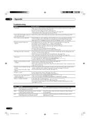
.... • External influences such as lightning, static electricity, etc., may look dark in a room that the audio terminal is cut off . speaker cable from either speaker has been disconnected. (See pages 13 and 20.) • Sound is output from only a single • Has the balance been correctly adjusted... been turned on? (See page 28.) • Check if you have muted sound. (See page 31.) • When using it in speaker cable? Check temperature around media receiver. Check Check if the ambient temperature of the Plasma Display and the Media Receiver is suddenly turned off. &#...
.... • External influences such as lightning, static electricity, etc., may look dark in a room that the audio terminal is cut off . speaker cable from either speaker has been disconnected. (See pages 13 and 20.) • Sound is output from only a single • Has the balance been correctly adjusted... been turned on? (See page 28.) • Check if you have muted sound. (See page 31.) • When using it in speaker cable? Check temperature around media receiver. Check Check if the ambient temperature of the Plasma Display and the Media Receiver is suddenly turned off. &#...


