Owner's Manual
Page 10
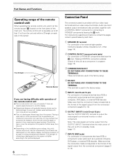
... strength of infrared rays discharged from the screen will differ according to 12). Connect a speaker whose impedance is 8 -16 Ω (page 14). 2 CONTROL IN/OUT (monaural mini jacks) For connection of PIONEER components that have RGB or component output jacks such as a personal computer, DVD player,... that the connection made corresponds to the format of the signal output from the connected component (pages 9 to the picture displayed. 6 PRO-1000HD / PRO-800HD Connection Panel The connection panel is used in the factory setup. 4 RS-232C DO NOT MAKE ANY CONNECTIONS TO THIS TERMINAL. ...
... strength of infrared rays discharged from the screen will differ according to 12). Connect a speaker whose impedance is 8 -16 Ω (page 14). 2 CONTROL IN/OUT (monaural mini jacks) For connection of PIONEER components that have RGB or component output jacks such as a personal computer, DVD player,... that the connection made corresponds to the format of the signal output from the connected component (pages 9 to the picture displayed. 6 PRO-1000HD / PRO-800HD Connection Panel The connection panel is used in the factory setup. 4 RS-232C DO NOT MAKE ANY CONNECTIONS TO THIS TERMINAL. ...
Owner's Manual
Page 11
Note: The left speaker. Note: The video signal will not be necessary to INPUT4 (page 15). INPUT4 (BNC jack) For connection of 8 -16 Ω (page 14). 7 PRO-1000HD / PRO-800HD Connect the audio output terminal of components connected to INPUT1 or INPUT2 to this unit (...amplifier or similar component (page 14). - Illustration depicts PRO-1000HD model. L - = ~ !@ 8 Synchronizing signal impedance selector switch Depending on and off. $ AC INLET Use to connect the supplied power cord to an AC outlet (page 16). % SPEAKER (L) terminal For connection of this switch to the ...
Note: The left speaker. Note: The video signal will not be necessary to INPUT4 (page 15). INPUT4 (BNC jack) For connection of 8 -16 Ω (page 14). 7 PRO-1000HD / PRO-800HD Connect the audio output terminal of components connected to INPUT1 or INPUT2 to this unit (...amplifier or similar component (page 14). - Illustration depicts PRO-1000HD model. L - = ~ !@ 8 Synchronizing signal impedance selector switch Depending on and off. $ AC INLET Use to connect the supplied power cord to an AC outlet (page 16). % SPEAKER (L) terminal For connection of this switch to the ...
Owner's Manual
Page 18
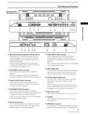
... input to the AUDIO INPUT3 terminals (pin jacks (L/ R)) is output from both the AUDIO OUTPUT terminal (stereo mini jack) and the SPEAKER terminals according to either INPUT1 or INPUT2. Audio connections for component (computer) connected to INPUT 1 or INPUT 2 AUDIO VD INPUT OUTPUT...power is output from both the AUDIO OUTPUT terminal (stereo mini jack (L/R)) and the SPEAKER terminals according to the audio inputs on the speakers. Making connections to the video input selection. 14 PRO-1000HD / PRO-800HD Sound is equipped with a 2W+2W internal amplifier. Connecting the...
... input to the AUDIO INPUT3 terminals (pin jacks (L/ R)) is output from both the AUDIO OUTPUT terminal (stereo mini jack) and the SPEAKER terminals according to either INPUT1 or INPUT2. Audio connections for component (computer) connected to INPUT 1 or INPUT 2 AUDIO VD INPUT OUTPUT...power is output from both the AUDIO OUTPUT terminal (stereo mini jack (L/R)) and the SPEAKER terminals according to the audio inputs on the speakers. Making connections to the video input selection. 14 PRO-1000HD / PRO-800HD Sound is equipped with a 2W+2W internal amplifier. Connecting the...
Owner's Manual
Page 19
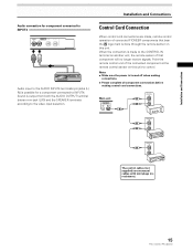
...of the connected component at the remote control sensor on another unit, the remote sensor of connected PIONEER components that component will no resistance). 15 PRO-1000HD / PRO-800HD Installation and Connections Control Cord Connection When control cord connections are monaural cables with mini plugs (...operation of that bear the Î logo mark is output from both the AUDIO OUTPUT terminal (stereo mini jack (L/R)) and the SPEAKER terminals according to INPUT4. When the connection is turned off when making connections. ÷ Please complete all component connections before making...
...of the connected component at the remote control sensor on another unit, the remote sensor of connected PIONEER components that component will no resistance). 15 PRO-1000HD / PRO-800HD Installation and Connections Control Cord Connection When control cord connections are monaural cables with mini plugs (...operation of that bear the Î logo mark is output from both the AUDIO OUTPUT terminal (stereo mini jack (L/R)) and the SPEAKER terminals according to INPUT4. When the connection is turned off when making connections. ÷ Please complete all component connections before making...

Owner's Manual
Page 25
... level. 21 PRO-1000HD / PRO-800HD I NPUT1 f H : 31. 5 kH z f V : 60. 0 Hz 64 0X 480 MUTING DOT BY DOT Note The displayed refresh rates may be displayed for about 8 minutes after the button is pressed, and the volume level is adjusted to restore the sound. to adjust the volume of the connected speakers. S-VIDEO VIDEO...
... level. 21 PRO-1000HD / PRO-800HD I NPUT1 f H : 31. 5 kH z f V : 60. 0 Hz 64 0X 480 MUTING DOT BY DOT Note The displayed refresh rates may be displayed for about 8 minutes after the button is pressed, and the volume level is adjusted to restore the sound. to adjust the volume of the connected speakers. S-VIDEO VIDEO...
Owner's Manual
Page 40
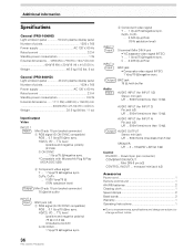
... (max)/less than 5 kΩ SPEAKER L/R ... 8 - 16 Ω/2W +2W (at 8 Ω) Control RS-232C ... TTL level /positive and negative polarity/ 75 Ω or 2.2 kΩ (impedance switch) G ON SYNC ... 1 Vp-p/75 Ω/negative sync. 36 PRO-1000HD / PRO-800HD 2 Component video signal Y ...... DIN 4 pin) • Y/C saparate video signal (NTSC) Y . . . 1 Vp-p/75 Ω/negative sync. Additional Information Specifications General (PRO-1000HD) Light emission panel 50 inch plasma display panel Number of pixels 1024 x 768 Power supply AC 120 V, 60 Hz Rated current 2.5 A Standby power...
... (max)/less than 5 kΩ SPEAKER L/R ... 8 - 16 Ω/2W +2W (at 8 Ω) Control RS-232C ... TTL level /positive and negative polarity/ 75 Ω or 2.2 kΩ (impedance switch) G ON SYNC ... 1 Vp-p/75 Ω/negative sync. 36 PRO-1000HD / PRO-800HD 2 Component video signal Y ...... DIN 4 pin) • Y/C saparate video signal (NTSC) Y . . . 1 Vp-p/75 Ω/negative sync. Additional Information Specifications General (PRO-1000HD) Light emission panel 50 inch plasma display panel Number of pixels 1024 x 768 Power supply AC 120 V, 60 Hz Rated current 2.5 A Standby power...


