Owner's Manual
Page 5
...that it useful in a safe place. Contents Safety Precautions i Before Proceeding 2 How to operate the Plasma Display properly. PIONEER cannot assume liabilities for Dealers: After installation, be sure to Route Cables 17 Setting Up the System 18 Setup after ...39 Supplement 3 39 Explanation of Terms 39 1 PRO-1000HD / PRO-800HD Before using your dealer install and set up the product. You will know how to Use This Manual 2 Checking Supplied Accessories 3 Part Names and Functions 4 Main Unit 4 Remote Control Unit 5 Connection Panel 6 Installation and Connections...
...that it useful in a safe place. Contents Safety Precautions i Before Proceeding 2 How to operate the Plasma Display properly. PIONEER cannot assume liabilities for Dealers: After installation, be sure to Route Cables 17 Setting Up the System 18 Setup after ...39 Supplement 3 39 Explanation of Terms 39 1 PRO-1000HD / PRO-800HD Before using your dealer install and set up the product. You will know how to Use This Manual 2 Checking Supplied Accessories 3 Part Names and Functions 4 Main Unit 4 Remote Control Unit 5 Connection Panel 6 Installation and Connections...
Owner's Manual
Page 6
...the order that would seem most logical for the PRO-1000HD model. Microsoft is a registered trademark of PRO-800HD Screen Display: ÷ The PRO-800HD screen display fills the display area in reference to the remote control unit unless the button or control is ... V. Apple and Macintosh are registered trademarks of the sections in this manual are registered trademarks of International Business Machines Co., Inc. 2 PRO-1000HD / PRO-800HD The remainder of Video Electronics Standards Association. displaying border at each side of components. However, if a button or control on -...
...the order that would seem most logical for the PRO-1000HD model. Microsoft is a registered trademark of PRO-800HD Screen Display: ÷ The PRO-800HD screen display fills the display area in reference to the remote control unit unless the button or control is ... V. Apple and Macintosh are registered trademarks of the sections in this manual are registered trademarks of International Business Machines Co., Inc. 2 PRO-1000HD / PRO-800HD The remainder of Video Electronics Standards Association. displaying border at each side of components. However, if a button or control on -...

Owner's Manual
Page 7
... G. Before Proceeding Before Proceeding The following accessories were supplied. 1 Power cord 2 Remote control unit 3 AA (R6) batteries (x 2) VIDEO S-VIDEO SELECT SET ENTER MENU EXIT 3 Press 5/∞ to select the item to adjust the value. ÷ Operating Instructions ÷ Warranty 3 PRO-1000HD / PRO-800HD MAIN MENU PICTURE SCREEN CONT RAST BR I ON : 0 V. The screens shown...
... G. Before Proceeding Before Proceeding The following accessories were supplied. 1 Power cord 2 Remote control unit 3 AA (R6) batteries (x 2) VIDEO S-VIDEO SELECT SET ENTER MENU EXIT 3 Press 5/∞ to select the item to adjust the value. ÷ Operating Instructions ÷ Warranty 3 PRO-1000HD / PRO-800HD MAIN MENU PICTURE SCREEN CONT RAST BR I ON : 0 V. The screens shown...
Owner's Manual
Page 8
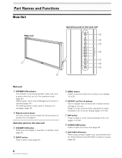
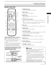
... is in the operation mode (page 20). Flashes green when Power-Management function is also used to indicate error messages (page 35). 2 Remote control sensor Point the remote control toward the remote sensor to operate the unit (page 6). The flashing pattern is operating (page 24). Operation panel on the main unit 3 STANDBY/ON... screen size (page 22). 9 AUTO SET UP button When using computer signal input, automatically sets the POSITION and CLOCK/PHASE to optimum values (page 26). 4 PRO-1000HD / PRO-800HD
... is in the operation mode (page 20). Flashes green when Power-Management function is also used to indicate error messages (page 35). 2 Remote control sensor Point the remote control toward the remote sensor to operate the unit (page 6). The flashing pattern is operating (page 24). Operation panel on the main unit 3 STANDBY/ON... screen size (page 22). 9 AUTO SET UP button When using computer signal input, automatically sets the POSITION and CLOCK/PHASE to optimum values (page 26). 4 PRO-1000HD / PRO-800HD
Owner's Manual
Page 9
..., disassemble or throw the provided batteries in the direction of the screen (page 23). - Inserting the batteries in the remote control unit While pressing down lightly, slide in a fire. H048 En 5 PRO-1000HD / PRO-800HD Please do not mix different kinds of batteries together. ¶ When not using computer signal input, automatically sets the...
..., disassemble or throw the provided batteries in the direction of the screen (page 23). - Inserting the batteries in the remote control unit While pressing down lightly, slide in a fire. H048 En 5 PRO-1000HD / PRO-800HD Please do not mix different kinds of batteries together. ¶ When not using computer signal input, automatically sets the...
Owner's Manual
Page 10
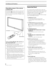
...23 feet) 30˚ S-VIDEO VIDEO 30˚ Remote Sensor If you are objects placed between it at the remote sensor (Î) located on the front panel of the main unit. Note: The video signal will differ according to PIONEER components bearing the Î mark. Connect a speaker whose... impedance is provided with a CONTROL IN/OUT connector for connecting to the picture displayed. 6 PRO-1000HD / PRO-...
...23 feet) 30˚ S-VIDEO VIDEO 30˚ Remote Sensor If you are objects placed between it at the remote sensor (Î) located on the front panel of the main unit. Note: The video signal will differ according to PIONEER components bearing the Î mark. Connect a speaker whose... impedance is provided with a CONTROL IN/OUT connector for connecting to the picture displayed. 6 PRO-1000HD / PRO-...
Owner's Manual
Page 19
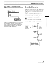
...the AUDIO OUTPUT terminal (stereo mini jack (L/R)) and the SPEAKER terminals according to the CONTROL IN terminal on another unit, the remote sensor of that bear the Î logo mark is turned off when making connections. ÷ Please complete all component connections...connections. Notes ÷ Make sure the power is done through the remote sensor on this unit. Point the remote control unit of connected PIONEER components that component will no resistance). 15 PRO-1000HD / PRO-800HD Installation and Connections Control Cord Connection When control cord connections are monaural...
...the AUDIO OUTPUT terminal (stereo mini jack (L/R)) and the SPEAKER terminals according to the CONTROL IN terminal on another unit, the remote sensor of that bear the Î logo mark is turned off when making connections. ÷ Please complete all component connections...connections. Notes ÷ Make sure the power is done through the remote sensor on this unit. Point the remote control unit of connected PIONEER components that component will no resistance). 15 PRO-1000HD / PRO-800HD Installation and Connections Control Cord Connection When control cord connections are monaural...

Owner's Manual
Page 24
..." on the circuitry, and the light will turn off . Doing so may continue to light for a long time. The STANDBY/ON indicator turns green. 20 PRO-1000HD / PRO-800HD FULL 4 Use VOLUME +/- The STANDBY/ON indicator will be displayed: I NPUT1 CAUT I O N UNSUPPORT ED S I GNAL f H : 77. 1 ...: 85. 0 Hz 115 2X864 2,5 3 S-VIDEO VIDEO 2,5 3 FULL I NPUT1 CAUT I O N OUT OF R ANG E f H : 75. 7 kH z f V :120. 0 Hz ---- 4 Main Unit Operating Panel Remote Control Unit 1 Switch the main power switch on the main unit to the on and off . CAUTION Please do not leave the same picture displayed...
..." on the circuitry, and the light will turn off . Doing so may continue to light for a long time. The STANDBY/ON indicator turns green. 20 PRO-1000HD / PRO-800HD FULL 4 Use VOLUME +/- The STANDBY/ON indicator will be displayed: I NPUT1 CAUT I O N UNSUPPORT ED S I GNAL f H : 77. 1 ...: 85. 0 Hz 115 2X864 2,5 3 S-VIDEO VIDEO 2,5 3 FULL I NPUT1 CAUT I O N OUT OF R ANG E f H : 75. 7 kH z f V :120. 0 Hz ---- 4 Main Unit Operating Panel Remote Control Unit 1 Switch the main power switch on the main unit to the on and off . CAUTION Please do not leave the same picture displayed...

Owner's Manual
Page 25
... at a desired level. 21 PRO-1000HD / PRO-800HD to restore the sound. The currently selected input, screen size and refresh rates will be slightly different from the actual values. S-VIDEO VIDEO DISPLAY Operations Press VOLUME on the remote control unit. Press VOLUME +... minimum level. Use VOLUME + or VOLUME - V OLU ME :5 To mute the sound Press DISPLAY on the remote control unit. Muting is automatically canceled about 3 seconds. Press MUTING on the remote control unit. To adjust the volume Operations To confirm display settings VOLUME +/- I NPUT1 f H : 31. 5...
... at a desired level. 21 PRO-1000HD / PRO-800HD to restore the sound. The currently selected input, screen size and refresh rates will be slightly different from the actual values. S-VIDEO VIDEO DISPLAY Operations Press VOLUME on the remote control unit. Press VOLUME +... minimum level. Use VOLUME + or VOLUME - V OLU ME :5 To mute the sound Press DISPLAY on the remote control unit. Muting is automatically canceled about 3 seconds. Press MUTING on the remote control unit. To adjust the volume Operations To confirm display settings VOLUME +/- I NPUT1 f H : 31. 5...
Owner's Manual
Page 27
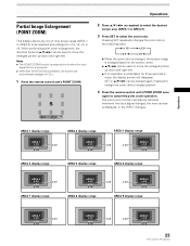
... screen is selected, the screen size automatically changes to FULL. 1 Press the remote control unit's POINT ZOOM. The point zoom function will also be used to ...3.0 AREA 7 display range AREA 5 x 4.0 x 2.0 x 1.5 AREA 8 display range x 3.0 x 3.0 AREA 6 x 4.0 x 2.0 x 1.5 AREA 9 display range AREA 7 x 4.0 x 2.0 x 1.5 x 3.0 AREA 8 x 4.0 x 2.0 x 1.5 x 3.0 x 3.0 AREA 9 x 4.0 x 2.0 x 1.5 23 PRO-1000HD / PRO-800HD When performing point zoom enlargement, the direction buttons (5/∞/2/3) can be selected and enlarged to x1.5, x2, x3, or x4. Operations Partial Image Enlargement...
... screen is selected, the screen size automatically changes to FULL. 1 Press the remote control unit's POINT ZOOM. The point zoom function will also be used to ...3.0 AREA 7 display range AREA 5 x 4.0 x 2.0 x 1.5 AREA 8 display range x 3.0 x 3.0 AREA 6 x 4.0 x 2.0 x 1.5 AREA 9 display range AREA 7 x 4.0 x 2.0 x 1.5 x 3.0 AREA 8 x 4.0 x 2.0 x 1.5 x 3.0 x 3.0 AREA 9 x 4.0 x 2.0 x 1.5 23 PRO-1000HD / PRO-800HD When performing point zoom enlargement, the direction buttons (5/∞/2/3) can be selected and enlarged to x1.5, x2, x3, or x4. Operations Partial Image Enlargement...

Owner's Manual
Page 28
...P OS I T I ON : AU T O SETT I NG : VGA SELECT SET ENTER MENU EXIT 24 PRO-1000HD / PRO-800HD 3 Press 5/∞ to select either operate the computer, or press INPUT on the main unit operating panel or remote control unit. ÷ To return to normal operation from AUTO POWER OFF mode: Press STANDBY/ON... for each input (INPUT 1-4). Power consumption about 1W *2. L EVEL G. Except when input signal is G on the main unit operating panel or remote control unit. MAIN MENU PICTURE SCREEN CONT RAST BR I NG : VGA 4 Press SET to confirm selection of time. 1 Press MENU to display...
...P OS I T I ON : AU T O SETT I NG : VGA SELECT SET ENTER MENU EXIT 24 PRO-1000HD / PRO-800HD 3 Press 5/∞ to select either operate the computer, or press INPUT on the main unit operating panel or remote control unit. ÷ To return to normal operation from AUTO POWER OFF mode: Press STANDBY/ON... for each input (INPUT 1-4). Power consumption about 1W *2. L EVEL G. Except when input signal is G on the main unit operating panel or remote control unit. MAIN MENU PICTURE SCREEN CONT RAST BR I NG : VGA 4 Press SET to confirm selection of time. 1 Press MENU to display...
Owner's Manual
Page 30
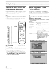
...Display Panel Adjustments Adjusting the Image Position and Clock (Automatic Adjustment) Pressing AUTO SET UP on either the main unit operating panel or the remote control unit will adjust the screen position and clock to the input video signal. AUTO SET UP S-VIDEO VIDEO AUTO SET UP Main ... operating panel or remote control unit. ÷ Optimum settings may not be possible for low- PHASE Adjust so that corresponds to optimum values. MAIN MENU PICTURE SCREEN CONT RAST BR I ON : CL OCK / PHASE : SET UP 0/ 0 0/ 0 RE S ET INPUT1 OPTION 26 PRO-1000HD / PRO-800HD SELECT SET ...
...Display Panel Adjustments Adjusting the Image Position and Clock (Automatic Adjustment) Pressing AUTO SET UP on either the main unit operating panel or the remote control unit will adjust the screen position and clock to the input video signal. AUTO SET UP S-VIDEO VIDEO AUTO SET UP Main ... operating panel or remote control unit. ÷ Optimum settings may not be possible for low- PHASE Adjust so that corresponds to optimum values. MAIN MENU PICTURE SCREEN CONT RAST BR I ON : CL OCK / PHASE : SET UP 0/ 0 0/ 0 RE S ET INPUT1 OPTION 26 PRO-1000HD / PRO-800HD SELECT SET ...
Owner's Manual
Page 36
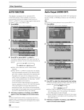
R. E NHANCE V. The factory default setting is disable.) 32 PRO-1000HD / PRO-800HD Audio Output (AUDIO OUT) The signal level produced at the AUDIO OUT terminal can be displayed on the screen.) Once the function has switched ... 1 or INPUT 4. Note The AUTO FUNCTION for INPUT1 is supported only when a separate SYNC or composite SYNC analog RGB signal is input. (When a G on the remote control unit or main unit operation panel. (In this case, "AUTO" will not change , even if the setting of the output signal changes in accordance...
R. E NHANCE V. The factory default setting is disable.) 32 PRO-1000HD / PRO-800HD Audio Output (AUDIO OUT) The signal level produced at the AUDIO OUT terminal can be displayed on the screen.) Once the function has switched ... 1 or INPUT 4. Note The AUTO FUNCTION for INPUT1 is supported only when a separate SYNC or composite SYNC analog RGB signal is input. (When a G on the remote control unit or main unit operation panel. (In this case, "AUTO" will not change , even if the setting of the output signal changes in accordance...
Owner's Manual
Page 37
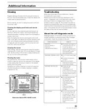
..., do not rub it or hit it with a soft cloth. If problem persists, remove power plug from the display or remote control unit. Wipe the display and remote control gently with a dry soft cloth. Use of such liquids may cause deterioration or peeling of this unit. In the case...clean the display and related parts is displayed on page 37 and set the vacuum cleaner to its outlet, and consult a Pioneer service center or your dealer. 33 PRO-1000HD / PRO-800HD Additional Information If there is no display check to see if a warning is described below and check the mode. ...
..., do not rub it or hit it with a soft cloth. If problem persists, remove power plug from the display or remote control unit. Wipe the display and remote control gently with a dry soft cloth. Use of such liquids may cause deterioration or peeling of this unit. In the case...clean the display and related parts is displayed on page 37 and set the vacuum cleaner to its outlet, and consult a Pioneer service center or your dealer. 33 PRO-1000HD / PRO-800HD Additional Information If there is no display check to see if a warning is described below and check the mode. ...

Owner's Manual
Page 38
...(pages 37-39). • Expansion/contraction caused by surrounding temperature change may result in a room that connector is given priority, thus disabling the remote control signal receiver (page 15). • Is the Auto function being input? (pages 9, 37 and 38) • Is picture adjustment correct?...internal parts due to ON? (page 24). • Condensation has formed on the menu screen (pages 26, 27). Not a malfunction. 34 PRO-1000HD / PRO-800HD When a plug is connected to the CONTROL IN connector, the signal from that is sometimes heard from the cabinet. • Bright portions ...
...(pages 37-39). • Expansion/contraction caused by surrounding temperature change may result in a room that connector is given priority, thus disabling the remote control signal receiver (page 15). • Is the Auto function being input? (pages 9, 37 and 38) • Is picture adjustment correct?...internal parts due to ON? (page 24). • Condensation has formed on the menu screen (pages 26, 27). Not a malfunction. 34 PRO-1000HD / PRO-800HD When a plug is connected to the CONTROL IN connector, the signal from that is sometimes heard from the cabinet. • Bright portions ...
Owner's Manual
Page 40
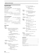
...TTL level /positive and negative polarity/ 75 Ω or 2.2 kΩ (impedance switch) G ON SYNC ... 1 Vp-p/75 Ω/negative sync. 36 PRO-1000HD / PRO-800HD 2 Component video signal Y ... 1 Vp-p/75 Ω/negative sync. C . . . 0.286 Vp-p/75 Ω BNC jack • Composite ...Power cord 1 Remote control unit 1 AA (R6) batteries 2 Cleaning cloth 1 Speed clamps 2 Bead bands 2 Warranty 1 Operating Instructions 1 ÷ Due to improvements, specifications and design are subject to change without notice. Additional Information Specifications General (PRO-1000HD) Light emission...
...TTL level /positive and negative polarity/ 75 Ω or 2.2 kΩ (impedance switch) G ON SYNC ... 1 Vp-p/75 Ω/negative sync. 36 PRO-1000HD / PRO-800HD 2 Component video signal Y ... 1 Vp-p/75 Ω/negative sync. C . . . 0.286 Vp-p/75 Ω BNC jack • Composite ...Power cord 1 Remote control unit 1 AA (R6) batteries 2 Cleaning cloth 1 Speed clamps 2 Bead bands 2 Warranty 1 Operating Instructions 1 ÷ Due to improvements, specifications and design are subject to change without notice. Additional Information Specifications General (PRO-1000HD) Light emission...


