Service Manual
Page 1
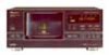
... SERVICE, INC. RRV2106 ¶ Refer to the service manual RRV2085 for PD-F958/KUXQ/CA. CONTRAST OF MISCELLANEOUS PARTS ..... 3 3. PIONEER ELECTRONIC (EUROPE) N.V. LTD. 253 Alexandra Road, #04-01, Singapore 159936 PIONEER ELECTRONIC CORPORATION 1999 T-ZZR FEB. 1999 Printed in Japan Type Model PD-F958 Power Requirement Remarks MYXQ O AC220-230V MVXQ O AC220-230V CONTENTS 1. THIS MANUAL IS...
... SERVICE, INC. RRV2106 ¶ Refer to the service manual RRV2085 for PD-F958/KUXQ/CA. CONTRAST OF MISCELLANEOUS PARTS ..... 3 3. PIONEER ELECTRONIC (EUROPE) N.V. LTD. 253 Alexandra Road, #04-01, Singapore 159936 PIONEER ELECTRONIC CORPORATION 1999 T-ZZR FEB. 1999 Printed in Japan Type Model PD-F958 Power Requirement Remarks MYXQ O AC220-230V MVXQ O AC220-230V CONTENTS 1. THIS MANUAL IS...

Service Manual
Page 3
Mark No. Symbol and Description KUXQ/CA type Part No. PD-F958 2. in our Master Spare Parts List. ÷ The mark found on the exploded diagram, Refer to use parts of the part. Ex. 1 When there are not in the service manual for the following examples. MYXQ type MVXQ type ... high precision metal film resistors). 5.62k Ω = 562 × 10 1 = 5621 RN1/4PC 5 6 2 1 F 7 CONTRAST OF PD-F958/KUXQ/CA, MYXQ and MVXQ PD-F958/ MYXQ, MVXQ and KUXQ/CA are constructed the same except for the base model. ÷ When ordering resistors, first convert resistance values into...
Mark No. Symbol and Description KUXQ/CA type Part No. PD-F958 2. in our Master Spare Parts List. ÷ The mark found on the exploded diagram, Refer to use parts of the part. Ex. 1 When there are not in the service manual for the following examples. MYXQ type MVXQ type ... high precision metal film resistors). 5.62k Ω = 562 × 10 1 = 5621 RN1/4PC 5 6 2 1 F 7 CONTRAST OF PD-F958/KUXQ/CA, MYXQ and MVXQ PD-F958/ MYXQ, MVXQ and KUXQ/CA are constructed the same except for the base model. ÷ When ordering resistors, first convert resistance values into...
Service Manual
Page 5
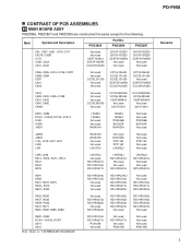
... RD1/4PU102J RD1/4PU471J RD1/4PU223J Not used Not used L395, L396 R310- PD-F958 CONTRAST OF PCB ASSEMBLIES H MAIN BOARD ASSY PWZ3896, PWZ3897 and PWZ3895 are constructed the same except for the following: Mark Symbol and Description PWZ3895 Part No. C438 C431, C432 C481, C482 CN401 Not used Not used Not used...
... RD1/4PU102J RD1/4PU471J RD1/4PU223J Not used Not used L395, L396 R310- PD-F958 CONTRAST OF PCB ASSEMBLIES H MAIN BOARD ASSY PWZ3896, PWZ3897 and PWZ3895 are constructed the same except for the following: Mark Symbol and Description PWZ3895 Part No. C438 C431, C432 C481, C482 CN401 Not used Not used Not used...

Service Manual
Page 6
... Note : Refer to "3.SCHEMATIC DIAGRAM". Not used Not used CKCYF103Z50 DE010WE0 Note : Refer to "3.SCHEMATIC DIAGRAM". PD-F958 I POWER BOARD ASSY PWZ3901 and PWZ3900 are constructed the same except for the following: Mark Symbol and Description Part No. PWZ3904 PWZ3905 NSP C714 J703 Not used Not used PCX1019 RD1/4PU471J Remarks Remarks Remarks...
... Note : Refer to "3.SCHEMATIC DIAGRAM". Not used Not used CKCYF103Z50 DE010WE0 Note : Refer to "3.SCHEMATIC DIAGRAM". PD-F958 I POWER BOARD ASSY PWZ3901 and PWZ3900 are constructed the same except for the following: Mark Symbol and Description Part No. PWZ3904 PWZ3905 NSP C714 J703 Not used Not used PCX1019 RD1/4PU471J Remarks Remarks Remarks...

Service Manual
Page 7
Description Part No. P HADPHONE BOARD ASSY (PWZ3910) COILS AND FILTERS L501, L504, L505 (AXIAL INDUCTOR) LAUR22J CAPACITORS C503, C504 CKCYF473Z50 RESISTORS VR501 (0.5kΩΒ) PCS1003 OTHERS JA501 J501 HADPHONE JACK 3P Cable Holder 2mm JUMPER WIRE RKN1002 51048-0300 D20PDY0315E PD-F958 7 ¶ PCB PARTS LIST Mark No.
Description Part No. P HADPHONE BOARD ASSY (PWZ3910) COILS AND FILTERS L501, L504, L505 (AXIAL INDUCTOR) LAUR22J CAPACITORS C503, C504 CKCYF473Z50 RESISTORS VR501 (0.5kΩΒ) PCS1003 OTHERS JA501 J501 HADPHONE JACK 3P Cable Holder 2mm JUMPER WIRE RKN1002 51048-0300 D20PDY0315E PD-F958 7 ¶ PCB PARTS LIST Mark No.

Service Manual
Page 11
... Diagrams Symbol in the schematic diagrams. 2. Viewpoint of PCB and schematic diagrams is shown below. Board Chip Part SIDE B H F CN401 P HEAD PHONE BOARD ASSY SIDE A 4 PD-F958 A B C PNP1455-B D A B C D E P 11 1 2 3 4 Part numbers in PCB diagrams match those in Schematic Diagrams Part Name B C EB C E BCE Transistor BCE B C EB C E Transistor with the schematic diagram. 4. A comparison between the main...
... Diagrams Symbol in the schematic diagrams. 2. Viewpoint of PCB and schematic diagrams is shown below. Board Chip Part SIDE B H F CN401 P HEAD PHONE BOARD ASSY SIDE A 4 PD-F958 A B C PNP1455-B D A B C D E P 11 1 2 3 4 Part numbers in PCB diagrams match those in Schematic Diagrams Part Name B C EB C E BCE Transistor BCE B C EB C E Transistor with the schematic diagram. 4. A comparison between the main...


