Service Manual
Page 1
...-8654, Japan PIONEER ELECTRONICS SERVICE, INC. PIONEER ELECTRONIC (EUROPE) N.V. Type Model PD-F958 Power Requirement Remarks MYXQ O AC220-230V MVXQ O AC220-230V CONTENTS 1. Haven 1087, Keetberglaan 1, 9120 Melsele, Belgium PIONEER ELECTRONICS ASIACENTRE PTE. THIS MANUAL IS APPLICABLE TO THE FOLLOWING MODEL(S) AND TYPE(S). RRV2106 ¶ Refer to the service manual RRV2085 for PD-F958/KUXQ/CA. CONTRAST OF MISCELLANEOUS PARTS ..... 3 3. SCHEMATIC DIAGRAM 8 4. FILE-TYPE COMPACT DISC PLAYER PD-F958 ORDER NO. Box...
...-8654, Japan PIONEER ELECTRONICS SERVICE, INC. PIONEER ELECTRONIC (EUROPE) N.V. Type Model PD-F958 Power Requirement Remarks MYXQ O AC220-230V MVXQ O AC220-230V CONTENTS 1. Haven 1087, Keetberglaan 1, 9120 Melsele, Belgium PIONEER ELECTRONICS ASIACENTRE PTE. THIS MANUAL IS APPLICABLE TO THE FOLLOWING MODEL(S) AND TYPE(S). RRV2106 ¶ Refer to the service manual RRV2085 for PD-F958/KUXQ/CA. CONTRAST OF MISCELLANEOUS PARTS ..... 3 3. SCHEMATIC DIAGRAM 8 4. FILE-TYPE COMPACT DISC PLAYER PD-F958 ORDER NO. Box...

Service Manual
Page 2
... connected to properly and safely repair complex products such as those covered by the system microprocessor, and the design prevents laser diode oscillation when the switch (S651) is not on the service manual RRV2085. 2 Laser diode oscillation will no longer function if the switch (S651) is opened, close viewing of the switch (S651) for (PD-F958/MYXQ and PD-F958/MVXQ types) PD-F958...
... connected to properly and safely repair complex products such as those covered by the system microprocessor, and the design prevents laser diode oscillation when the switch (S651) is not on the service manual RRV2085. 2 Laser diode oscillation will no longer function if the switch (S651) is opened, close viewing of the switch (S651) for (PD-F958/MYXQ and PD-F958/MVXQ types) PD-F958...

Service Manual
Page 3
... in our Master Spare Parts List. ÷ The mark found on the exploded diagram, Refer to use parts of the part. in the service manual for the following examples. Symbol and Description KUXQ/CA type Part No. indicate the pages and Nos. PD-F958 2. Mark No. Ex. 1 When there are 2 effective digits (any digit apart from 0), such as 560 ohm and 47k ohm (tolerance is...
... in our Master Spare Parts List. ÷ The mark found on the exploded diagram, Refer to use parts of the part. in the service manual for the following examples. Symbol and Description KUXQ/CA type Part No. indicate the pages and Nos. PD-F958 2. Mark No. Ex. 1 When there are 2 effective digits (any digit apart from 0), such as 560 ohm and 47k ohm (tolerance is...

Service Manual
Page 4
PD-F958 EXPLODED VIEWS PACKING SECTION Operating lnstructions No.10 No.11 Protecter (FL) Protecter (RL) Front Protecter (FR) Protecter (RR) Control Cable PD-F958/MVXQ only No.9 No.12 Packing Case EXTERIOR and FRONT PANEL SECTION PD-F958/MYXQ only No.6 No.5 AC Power Cord No.2 Cord Stopper Fuse Holder PD-F958/MVXQ only PD-F958/MVXQ only No.7 Rear Base Under Base No.4 Operation Panel No.8 Screw (IBZ30P080FZK) No.1 lnsulator Screw (IBZ30P080FZK) No.3 4
PD-F958 EXPLODED VIEWS PACKING SECTION Operating lnstructions No.10 No.11 Protecter (FL) Protecter (RL) Front Protecter (FR) Protecter (RR) Control Cable PD-F958/MVXQ only No.9 No.12 Packing Case EXTERIOR and FRONT PANEL SECTION PD-F958/MYXQ only No.6 No.5 AC Power Cord No.2 Cord Stopper Fuse Holder PD-F958/MVXQ only PD-F958/MVXQ only No.7 Rear Base Under Base No.4 Operation Panel No.8 Screw (IBZ30P080FZK) No.1 lnsulator Screw (IBZ30P080FZK) No.3 4
Service Manual
Page 5
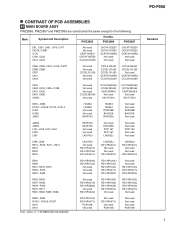
.../4PU471J PSS1008 Not used Not used RD1/4PU471J Not used PSS1008 Not used Not used Not used R487- PD-F958 CONTRAST OF PCB ASSEMBLIES H MAIN BOARD ASSY PWZ3896, PWZ3897 and PWZ3895 are constructed the same except for the following: Mark Symbol and Description PWZ3895 Part No. C438 C431, C432 C481, C482 CN401 Not used Not used Not used CCCSL390J50 Not used CCCCH220J50 CCCSL390J50...
.../4PU471J PSS1008 Not used Not used RD1/4PU471J Not used PSS1008 Not used Not used Not used R487- PD-F958 CONTRAST OF PCB ASSEMBLIES H MAIN BOARD ASSY PWZ3896, PWZ3897 and PWZ3895 are constructed the same except for the following: Mark Symbol and Description PWZ3895 Part No. C438 C431, C432 C481, C482 CN401 Not used Not used Not used CCCSL390J50 Not used CCCCH220J50 CCCSL390J50...

Service Manual
Page 6
... the following : Mark Symbol and Description Part No. PWZ3907 PWZ3908 D751 R751 Note : Refer to "3.SCHEMATIC DIAGRAM". L SWITCH BOARD ASSY PWZ3908 and PWZ3907 are constructed the same except for the following: Mark Symbol and Description Part No. PWZ3904 PWZ3905 NSP C714 J703 Not used Not used CKCYF103Z50 DE010WE0 Note : Refer to "3.SCHEMATIC DIAGRAM". PD-F958 I POWER BOARD ASSY PWZ3901 and PWZ3900 are...
... the following : Mark Symbol and Description Part No. PWZ3907 PWZ3908 D751 R751 Note : Refer to "3.SCHEMATIC DIAGRAM". L SWITCH BOARD ASSY PWZ3908 and PWZ3907 are constructed the same except for the following: Mark Symbol and Description Part No. PWZ3904 PWZ3905 NSP C714 J703 Not used Not used CKCYF103Z50 DE010WE0 Note : Refer to "3.SCHEMATIC DIAGRAM". PD-F958 I POWER BOARD ASSY PWZ3901 and PWZ3900 are...

Service Manual
Page 7
P HADPHONE BOARD ASSY (PWZ3910) COILS AND FILTERS L501, L504, L505 (AXIAL INDUCTOR) LAUR22J CAPACITORS C503, C504 CKCYF473Z50 RESISTORS VR501 (0.5kΩΒ) PCS1003 OTHERS JA501 J501 HADPHONE JACK 3P Cable Holder 2mm JUMPER WIRE RKN1002 51048-0300 D20PDY0315E PD-F958 7 ¶ PCB PARTS LIST Mark No. Description Part No.
P HADPHONE BOARD ASSY (PWZ3910) COILS AND FILTERS L501, L504, L505 (AXIAL INDUCTOR) LAUR22J CAPACITORS C503, C504 CKCYF473Z50 RESISTORS VR501 (0.5kΩΒ) PCS1003 OTHERS JA501 J501 HADPHONE JACK 3P Cable Holder 2mm JUMPER WIRE RKN1002 51048-0300 D20PDY0315E PD-F958 7 ¶ PCB PARTS LIST Mark No. Description Part No.

Service Manual
Page 9
H F9 5 6 7 8 5 6 7 8 PD-F958 A 1.6V 10 1.6V 0V 0V -9.2 0V -9.2 0V 0V LINE OUT JACK P B PD-F958/MVXQ Only PD-F958/MYXQ Only C H F MAIN BOARD ASSY (PWZ3896:PD-F958/MYXQ) (PWZ3897:PD-F958/MVXQ) TO POWER BOARD ASSY J11 FI PD-F958/MYXQ Only D Note: The numbers marked with a circle show the number of each measuring point, which correspond to the number in the service manual PD-F958 (ORDER NO. RRV2085) on page12 .
H F9 5 6 7 8 5 6 7 8 PD-F958 A 1.6V 10 1.6V 0V 0V -9.2 0V -9.2 0V 0V LINE OUT JACK P B PD-F958/MVXQ Only PD-F958/MYXQ Only C H F MAIN BOARD ASSY (PWZ3896:PD-F958/MYXQ) (PWZ3897:PD-F958/MVXQ) TO POWER BOARD ASSY J11 FI PD-F958/MYXQ Only D Note: The numbers marked with a circle show the number of each measuring point, which correspond to the number in the service manual PD-F958 (ORDER NO. RRV2085) on page12 .

Service Manual
Page 11
... A 4 PD-F958 A B C PNP1455-B D A B C D E P 11 1 2 3 4 A comparison between the main parts of PCB diagrams Connector Capacitor SIDE A P. The parts mounted on this PCB include all necessary parts for respective destinations, be sure to check with resistor DGS D G SD G S Field effect transistor Resistor array 3-terminal regulator 3. PCB CONNECTION DIAGRAM NOTE FOR PCB DIAGRAMS: 1. For further information for several destination. Part numbers in PCB diagrams match...
... A 4 PD-F958 A B C PNP1455-B D A B C D E P 11 1 2 3 4 A comparison between the main parts of PCB diagrams Connector Capacitor SIDE A P. The parts mounted on this PCB include all necessary parts for respective destinations, be sure to check with resistor DGS D G SD G S Field effect transistor Resistor array 3-terminal regulator 3. PCB CONNECTION DIAGRAM NOTE FOR PCB DIAGRAMS: 1. For further information for several destination. Part numbers in PCB diagrams match...


