Service Manual
Page 2
... which does not have special safety related characteristics. Health & Safety Code Section 25249.6 - Plug the AC line cord of , PIONEER Service Manual may be obtained at a nominal charge from visual inspection nor the protection afforded by them necessarily can adversely affect the ...;me désignation. (fusible de type lent) sur CCI indiquent que les (FOR USA MODEL ONLY) 1. MJ-D707, MJ-17D 1. Improperly performed repairs can be above 0.5 mA Test all exposed metal parts of the appliance (input/output terminals, screwheads, metal overlays, control shaft, etc.). SAFETY PRECAUTIONS...
... which does not have special safety related characteristics. Health & Safety Code Section 25249.6 - Plug the AC line cord of , PIONEER Service Manual may be obtained at a nominal charge from visual inspection nor the protection afforded by them necessarily can adversely affect the ...;me désignation. (fusible de type lent) sur CCI indiquent que les (FOR USA MODEL ONLY) 1. MJ-D707, MJ-17D 1. Improperly performed repairs can be above 0.5 mA Test all exposed metal parts of the appliance (input/output terminals, screwheads, metal overlays, control shaft, etc.). SAFETY PRECAUTIONS...

Service Manual
Page 41
MJ-D707, MJ-17D 6. ADJUSTMENT JIGS AND MEASURING INSTRUMENTS Thermometer Oscilloscope Optical Power Meter Jitter Meter Test Disc For servo system adjustment GGF1328 (MMD-212) For recording/playback inspection GGF1328 (MMD-212), GGF1277, TGYS1 (or MMD-110), Commercial discs 6.1 NECESSARY ADJUSTMENT POINTS ...
MJ-D707, MJ-17D 6. ADJUSTMENT JIGS AND MEASURING INSTRUMENTS Thermometer Oscilloscope Optical Power Meter Jitter Meter Test Disc For servo system adjustment GGF1328 (MMD-212) For recording/playback inspection GGF1328 (MMD-212), GGF1277, TGYS1 (or MMD-110), Commercial discs 6.1 NECESSARY ADJUSTMENT POINTS ...

Service Manual
Page 42
... switch. 2) SYSTEM TEST will be made on the FL display. DSP ERROR1 DSP ERROR2 Contents Same operation as in the DSP IC not correct Operation check for other keys When each key is not possible. MJ-D707, MJ-17D 6.2 TEST MODE There are two test modes: test mode 1 for main... unit operation check and test mode 2 for MD mechanism assy adjustment and check. 6.2.1 Test Mode 1 (main unit operation check) How to the following table shall...
... switch. 2) SYSTEM TEST will be made on the FL display. DSP ERROR1 DSP ERROR2 Contents Same operation as in the DSP IC not correct Operation check for other keys When each key is not possible. MJ-D707, MJ-17D 6.2 TEST MODE There are two test modes: test mode 1 for main... unit operation check and test mode 2 for MD mechanism assy adjustment and check. 6.2.1 Test Mode 1 (main unit operation check) How to the following table shall...

Service Manual
Page 43
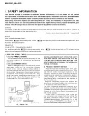
...-AMP) or IC104 (mechanical controller) has been exchanged or when a correction changing VD+3 has been made automatically from test mode to step 7. When the ambient temperature is over 25 °C, set to -3 79 - MJ-D707, MJ-17D 6.2.2 Test Mode 2 (MD Mechanism Assy Adjustment, Check) 1 Temperature Check (Please perform this check soon after the power has...
...-AMP) or IC104 (mechanical controller) has been exchanged or when a correction changing VD+3 has been made automatically from test mode to step 7. When the ambient temperature is over 25 °C, set to -3 79 - MJ-D707, MJ-17D 6.2.2 Test Mode 2 (MD Mechanism Assy Adjustment, Check) 1 Temperature Check (Please perform this check soon after the power has...

Service Manual
Page 44
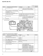
...) GTG : 4 to 4 or more. Operation Keys and Operation Method 1 Power ON while holding the ENTER key and the PLAY key depressed. MJ-D707, MJ-17D 3 Grating Adjustment Step No. 1 2 Operation Keys and Operation Method Power ON while holding the ENTER key and the PLAY key depressed. 2 Insert ...the test disc GGF1328 (MMD-212). 3 Press the REC MODE key (until the Lissajous waveform becomes as shown in tracking open status. (The servo is...
...) GTG : 4 to 4 or more. Operation Keys and Operation Method 1 Power ON while holding the ENTER key and the PLAY key depressed. MJ-D707, MJ-17D 3 Grating Adjustment Step No. 1 2 Operation Keys and Operation Method Power ON while holding the ENTER key and the PLAY key depressed. 2 Insert ...the test disc GGF1328 (MMD-212). 3 Press the REC MODE key (until the Lissajous waveform becomes as shown in tracking open status. (The servo is...

Service Manual
Page 45
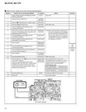
...GRT AJST 3 Press the REC MODE key (until deFO AJST is displayed). 4 Press the PLAY key. PEG : HAG: | Can't ADJ. Insert the test disc GGF1328 (MMD-212). 3 Press the REC MODE key (until AUTO AJST is recorded. 45 COMPLETE AUT YOBI EEPROM W Toc Reading GGF1328 (MMD-212) ... adjustment Step No. 1 2 Operation Keys and Operation Method Power ON while holding the ENTER key and the PLAY EJECT Test mode key depressed. 2 Insert the test disc GGF1328 (MMD-212). MJ-D707, MJ-17D Step No. 7 8 9 Operation Keys and Operation Method Press the STOP key. Press the REC MODE key (...
...GRT AJST 3 Press the REC MODE key (until deFO AJST is displayed). 4 Press the PLAY key. PEG : HAG: | Can't ADJ. Insert the test disc GGF1328 (MMD-212). 3 Press the REC MODE key (until AUTO AJST is recorded. 45 COMPLETE AUT YOBI EEPROM W Toc Reading GGF1328 (MMD-212) ... adjustment Step No. 1 2 Operation Keys and Operation Method Power ON while holding the ENTER key and the PLAY EJECT Test mode key depressed. 2 Insert the test disc GGF1328 (MMD-212). MJ-D707, MJ-17D Step No. 7 8 9 Operation Keys and Operation Method Press the STOP key. Press the REC MODE key (...
Service Manual
Page 46
... and fixed display is recorded. The jitter value (J-) at the time of the other setting limit is ended. EJECT Test mode Insert the test disc GGF1328 (MMD-212). TEST PLAY TEST PLAY mode Press the NAME key and display the inner circumference address. ADRES 0050 Press the PLAY key and display the... " (step 3, step 4). side is larger than J-, press the REC MODE key and display the C1 error when the focus offset is 200 or less. MJ-D707, MJ-17D Step No. 7 8 9 10 11 Operation Keys and Operation Method Press the NAME CLIP key. When J+ is larger than J+.) Change the value with ...
... and fixed display is recorded. The jitter value (J-) at the time of the other setting limit is ended. EJECT Test mode Insert the test disc GGF1328 (MMD-212). TEST PLAY TEST PLAY mode Press the NAME key and display the inner circumference address. ADRES 0050 Press the PLAY key and display the... " (step 3, step 4). side is larger than J-, press the REC MODE key and display the C1 error when the focus offset is 200 or less. MJ-D707, MJ-17D Step No. 7 8 9 10 11 Operation Keys and Operation Method Press the NAME CLIP key. When J+ is larger than J+.) Change the value with ...

Service Manual
Page 47
... a0062 c0009 a03d2 c0007 a0712 c0006 Check that the jitter value meets the standard value of the C1 error is ended. Test mode is ejected. Perform steps 6 to 9 in this condition. MJ-D707, MJ-17D Step No. 8 9 10 11 12 13 14 15 Operation Keys and Operation Method Press the REC key. Press ...the STOP key. Press the EJECT key, eject the test disc GGF1328 (MMD-212), and insert TGYS1 (or MMD-110.) Perform steps 3 to...
... a0062 c0009 a03d2 c0007 a0712 c0006 Check that the jitter value meets the standard value of the C1 error is ended. Test mode is ejected. Perform steps 6 to 9 in this condition. MJ-D707, MJ-17D Step No. 8 9 10 11 12 13 14 15 Operation Keys and Operation Method Press the REC key. Press ...the STOP key. Press the EJECT key, eject the test disc GGF1328 (MMD-212), and insert TGYS1 (or MMD-110.) Perform steps 3 to...
Service Manual
Page 48
...disc.) intermediate circumference. 9 Perform step 6. Jitter Meter LEVEL JITTER CORE MAIN UNIT ASSY SIDE A GND 48 EFM MON REFO Connection diagram Test mode is shifted (up to 10 times) according to 13 of " Jitter/C1 Error Check a0069 c0009 Check the jitter/C2 error ... and the EJECT Test mode PLAY key depressed. 2 Insert the test disc (GGF1277). TEST REC TEST REC mode 5 Press the NAME key and display the inner circumference address. outer circumference) has been used 1000 7 Press the NAME key and display the inner circumference address. MJ-D707, MJ-17D Jitter/C1...
...disc.) intermediate circumference. 9 Perform step 6. Jitter Meter LEVEL JITTER CORE MAIN UNIT ASSY SIDE A GND 48 EFM MON REFO Connection diagram Test mode is shifted (up to 10 times) according to 13 of " Jitter/C1 Error Check a0069 c0009 Check the jitter/C2 error ... and the EJECT Test mode PLAY key depressed. 2 Insert the test disc (GGF1277). TEST REC TEST REC mode 5 Press the NAME key and display the inner circumference address. outer circumference) has been used 1000 7 Press the NAME key and display the inner circumference address. MJ-D707, MJ-17D Jitter/C1...

Service Manual
Page 54
... supply 13 DGND - Digital GND 14 TEST0 15 TEST1 16 TEST2 I /O Description 17 X176KO O Clock output; Name I Test-use input; Analog power supply 3 EFMI I Test-use input; PWM 22 SLDRF O Slide servo forward output; PWM 25 SPDRR O Spindle servo reverse output or spindle rotation forward...signal 12 VDD1 - PWM 24 SPDRF O Spindle servo forward output or spindle servo output; PWM 20 TRDRF O Tracking servo forward output; MJ-D707, MJ-17D LR376481 (IC102: CORE MAIN UNIT ASSY) Encode/Decode/Atrac Pin Assignment (Top view) FEMON DADATA ADDATA DFCK BCLK LRCK DGND VDD3 DOUT...
... supply 13 DGND - Digital GND 14 TEST0 15 TEST1 16 TEST2 I /O Description 17 X176KO O Clock output; Name I Test-use input; Analog power supply 3 EFMI I Test-use input; PWM 22 SLDRF O Slide servo forward output; PWM 25 SPDRR O Spindle servo reverse output or spindle rotation forward...signal 12 VDD1 - PWM 24 SPDRF O Spindle servo forward output or spindle servo output; PWM 20 TRDRF O Tracking servo forward output; MJ-D707, MJ-17D LR376481 (IC102: CORE MAIN UNIT ASSY) Encode/Decode/Atrac Pin Assignment (Top view) FEMON DADATA ADDATA DFCK BCLK LRCK DGND VDD3 DOUT...


