Service Manual
Page 1
Service Manual ORDER NO. ADJUSTMENT 19 7. SCHEMATIC DIAGRAM 8 4. GENERAL INFORMATION 20 7.1 IC 20 7.2 DISASSEMBLY 21 7.3 BLOCK DIAGRAM 22 8. FEB. 1998 Printed in Japan OPERATIONS AND SPECIFICATIONS 23 PIONEER ELECTRONIC CORPORATION 4-1, Meguro 1-Chome, Meguro-ku, Tokyo 153-8654, Japan PIONEER ELECTRONICS SERVICE INC. EXPLODED VIEWS AND PARTS LIST 3 3. CRT2187 BRIDGEABLE POWER AMPLIFIER GM-X822 X1R/UC GM-X722 X1R/UC,ES,EW CONTENTS 1. SAFETY INFORMATION 2 2. ELECTRICAL PARTS LIST 15 6. P.O.Box 1760, Long...
Service Manual ORDER NO. ADJUSTMENT 19 7. SCHEMATIC DIAGRAM 8 4. GENERAL INFORMATION 20 7.1 IC 20 7.2 DISASSEMBLY 21 7.3 BLOCK DIAGRAM 22 8. FEB. 1998 Printed in Japan OPERATIONS AND SPECIFICATIONS 23 PIONEER ELECTRONIC CORPORATION 4-1, Meguro 1-Chome, Meguro-ku, Tokyo 153-8654, Japan PIONEER ELECTRONICS SERVICE INC. EXPLODED VIEWS AND PARTS LIST 3 3. CRT2187 BRIDGEABLE POWER AMPLIFIER GM-X822 X1R/UC GM-X722 X1R/UC,ES,EW CONTENTS 1. SAFETY INFORMATION 2 2. ELECTRICAL PARTS LIST 15 6. P.O.Box 1760, Long...
Service Manual
Page 2
...& Safety Code, Section 25249.5). Improperly performed repairs can adversely affect the safety and reliability of this manual. you are not qualified to properly and safely repair complex products such as a known reproductive toxicant which contain lead in this product is listed by the ... warranty. SAFETY INFORMATION UC model CAUTION This service manual is not meant for qualified service technicians; GM-X822,X722 1. WARNING Lead in solder used in solder, avoid unprotected skin contact with the solder. Also, when soldering do so and refer the repair to do not inhale any...
...& Safety Code, Section 25249.5). Improperly performed repairs can adversely affect the safety and reliability of this manual. you are not qualified to properly and safely repair complex products such as a known reproductive toxicant which contain lead in this product is listed by the ... warranty. SAFETY INFORMATION UC model CAUTION This service manual is not meant for qualified service technicians; GM-X822,X722 1. WARNING Lead in solder used in solder, avoid unprotected skin contact with the solder. Also, when soldering do so and refer the repair to do not inhale any...
Service Manual
Page 3
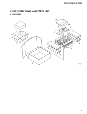
GM-X822,X722 2. EXPLODED VIEWS AND PARTS LIST 2.1 PACKING 10 9 3 11 24 1 7 6 8 5 8 Fig. 1 3
GM-X822,X722 2. EXPLODED VIEWS AND PARTS LIST 2.1 PACKING 10 9 3 11 24 1 7 6 8 5 8 Fig. 1 3
Service Manual
Page 4
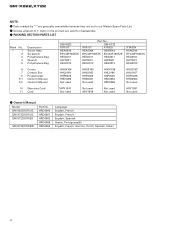
... Box 8 Protector(x2) 9-1 Owner's Manual 9-2 Owner's Manual HHG0164 HHL0164 HHP0025 HRD0060 Not used HHG0165 HHL0165 HHP0025 HRD0061 Not used HHG0166 HHL0166 HHP0025 HRD0062 HRD0069 HHG0167 HHL0167 HHP0025 HRD0063 Not used 10 Warranty Card 11 Card *HRY1070 Not used Not used ARY1048 Not used Not used HRY1087 Not used for disassembly. - Owner's Manual Model GM-X822/X1R/UC GM-X722/X1R/UC GM-X722/X1R/ES GM-X722/X1R/EW Part No.
... Box 8 Protector(x2) 9-1 Owner's Manual 9-2 Owner's Manual HHG0164 HHL0164 HHP0025 HRD0060 Not used HHG0165 HHL0165 HHP0025 HRD0061 Not used HHG0166 HHL0166 HHP0025 HRD0062 HRD0069 HHG0167 HHL0167 HHP0025 HRD0063 Not used 10 Warranty Card 11 Card *HRY1070 Not used Not used ARY1048 Not used Not used HRY1087 Not used for disassembly. - Owner's Manual Model GM-X822/X1R/UC GM-X722/X1R/UC GM-X722/X1R/ES GM-X722/X1R/EW Part No.
Service Manual
Page 6
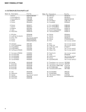
... Fan Motor 40 Fuse(20A) Part No. GM-X822,X722 (1) EXTERIOR SECTION PARTS LIST Mark No. BMZ30P250FZK CBA1323 CBA1382 CNM5854 HBA0006 6 Screw 7 Screw 8 Washer 9 Case 10 Heat Sink HBA0011 HBA0012 HBF0005 HNB0037 HNR0078 11 Window 12 Lighting Conductor 13 Amp Unit 14 Screw 15 Screw HNS0053 HNV0013 See Contrast table(2) BMS30P060FZK BMS30P080FMC 16 Clamper 17 Terminal(CN904) 18 Plug(CN551) 19 Plug(CN501) 20 Connector(CN503) CEF1009...
... Fan Motor 40 Fuse(20A) Part No. GM-X822,X722 (1) EXTERIOR SECTION PARTS LIST Mark No. BMZ30P250FZK CBA1323 CBA1382 CNM5854 HBA0006 6 Screw 7 Screw 8 Washer 9 Case 10 Heat Sink HBA0011 HBA0012 HBF0005 HNB0037 HNR0078 11 Window 12 Lighting Conductor 13 Amp Unit 14 Screw 15 Screw HNS0053 HNV0013 See Contrast table(2) BMS30P060FZK BMS30P080FMC 16 Clamper 17 Terminal(CN904) 18 Plug(CN551) 19 Plug(CN501) 20 Connector(CN503) CEF1009...
Service Manual
Page 7
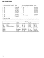
... HXA0271 HXA0272 NSPWF50S(VQ) 7 GM-X822,X722 (2) CONTRAST TABLE GM-X822/X1R/UC, GM-X722/X1R/UC, GM-X722/X1R/ES and GM-X722/X1R/EW are constructed the same except for the following: Mark No. 13 33 50 51 52 Symbol and Description Amp Unit Spacer Film Film Plate Unit GM-X822 X1R/UC HWH0075 HNM0053(x2) CNM5856 CNM5855 HXA0115 Part No.
... HXA0271 HXA0272 NSPWF50S(VQ) 7 GM-X822,X722 (2) CONTRAST TABLE GM-X822/X1R/UC, GM-X722/X1R/UC, GM-X722/X1R/ES and GM-X722/X1R/EW are constructed the same except for the following: Mark No. 13 33 50 51 52 Symbol and Description Amp Unit Spacer Film Film Plate Unit GM-X822 X1R/UC HWH0075 HNM0053(x2) CNM5856 CNM5855 HXA0115 Part No.
Service Manual
Page 8
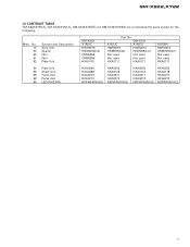
1 2 3 4 GM-X822,X722 3. A AMP PCB -10dBs -7.6dBs -10.2dBs B AUDIO PCB C BASS PCB B 15.5V -15.5V AMP UNIT Consists of AMP PCB AUDIO PCB BASS PCB -35V -35-30V C 30V -30V D A 8 1 2 3 4 SCHEMATIC DIAGRAM 3.1 AMP UNIT A Note: When ordering service parts, be sure to refer to "EXPLODED VIEWS AND PARTS LIST" or "ELECTRICAL PARTS LIST".
1 2 3 4 GM-X822,X722 3. A AMP PCB -10dBs -7.6dBs -10.2dBs B AUDIO PCB C BASS PCB B 15.5V -15.5V AMP UNIT Consists of AMP PCB AUDIO PCB BASS PCB -35V -35-30V C 30V -30V D A 8 1 2 3 4 SCHEMATIC DIAGRAM 3.1 AMP UNIT A Note: When ordering service parts, be sure to refer to "EXPLODED VIEWS AND PARTS LIST" or "ELECTRICAL PARTS LIST".
Service Manual
Page 12
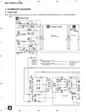
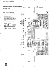
1 2 3 GM-X822,X722 4. Viewpoint of PCB diagrams Connector Capacitor B SIDE A P.C.Board Chip Part SIDE B INPUT B CN502 PREOUT C 4 A AMP PCB FAN MO D A 12 1 2 3 4 PCB CONNECTION DIAGRAM A 4.1 AMP UNIT NOTE FOR PCB DIAGRAMS 1. The parts mounted on this PCB include all necessary parts for respective destinations, be sure to check with the schematic diagram. 2. For further information for several destination.
1 2 3 GM-X822,X722 4. Viewpoint of PCB diagrams Connector Capacitor B SIDE A P.C.Board Chip Part SIDE B INPUT B CN502 PREOUT C 4 A AMP PCB FAN MO D A 12 1 2 3 4 PCB CONNECTION DIAGRAM A 4.1 AMP UNIT NOTE FOR PCB DIAGRAMS 1. The parts mounted on this PCB include all necessary parts for respective destinations, be sure to check with the schematic diagram. 2. For further information for several destination.
Service Manual
Page 13
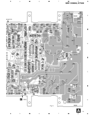
5 6 7 8 GM-X822,X722 A AN MOTOR B C C CN553 5 Fig. 5 6 7 D A 13 8
5 6 7 8 GM-X822,X722 A AN MOTOR B C C CN553 5 Fig. 5 6 7 D A 13 8
Service Manual
Page 18
...: Symbol and Description D902,903 LED S551 Switch S951 Switch VR552 Variable Resistor 50kΩ(C) R553,554 GM-X822 X1R/UC NSPWF50S(AQ) Not used Not used RD1/4PU222J RD1/4PU105J 18 GM-X722 X1R/UC X1R/ES NSPWF50S(VQ) NSPWF50S(VQ) Not used CSH1021 Not used HSH-156 Not used CCS1263 Not used RD1/4PU822J X1R/EW NSPWF50S(VQ) CSH1021...
...: Symbol and Description D902,903 LED S551 Switch S951 Switch VR552 Variable Resistor 50kΩ(C) R553,554 GM-X822 X1R/UC NSPWF50S(AQ) Not used Not used RD1/4PU222J RD1/4PU105J 18 GM-X722 X1R/UC X1R/ES NSPWF50S(VQ) NSPWF50S(VQ) Not used CSH1021 Not used HSH-156 Not used CCS1263 Not used RD1/4PU822J X1R/EW NSPWF50S(VQ) CSH1021...
Service Manual
Page 19
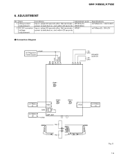
ADJUSTMENT No. Input ; GM-X822,X722 6. adjust 30 seconds after 1kΩ terminate power is switched on , and within 20 seconds. adjust 30 seconds after 1kΩ terminate power is switched on , and within 20 seconds. Connection Diagram +14.4V DC Regulated Power Supply 4Ω (2W) SPEAKER OUTPUT 4Ω (2W) POWER GND SYSTEM CONTROL VR951 mV Meter (1) mV Meter (2) VR201 R228 E Q213 C AMP UNIT GND VR101 1kΩ R L 1kΩ R128 mV...
ADJUSTMENT No. Input ; GM-X822,X722 6. adjust 30 seconds after 1kΩ terminate power is switched on , and within 20 seconds. adjust 30 seconds after 1kΩ terminate power is switched on , and within 20 seconds. Connection Diagram +14.4V DC Regulated Power Supply 4Ω (2W) SPEAKER OUTPUT 4Ω (2W) POWER GND SYSTEM CONTROL VR951 mV Meter (1) mV Meter (2) VR201 R228 E Q213 C AMP UNIT GND VR101 1kΩ R L 1kΩ R128 mV...
Service Manual
Page 20
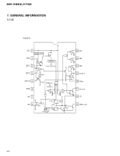
Oneshot (1µsec) SQ R 20µA + zz 2V 2V - + 12 Filter 11 Vs_out 10 TC 9 Mute_out 20 Circuit motion:on zz 50µA zz+- 16 IN1 2V zz+- 15 IN2 2V zz+- 14 IN3 2V 13 Cont_V DET_R 5 GND 6 NC 7 NC 8 - + 4.7kΩ Bandgap:on Switch:on zz + - 2V 5.6V 0.13V + - GENERAL INFORMATION 7.1 IC PA2027A VCC 1 Transient voltage detector Stby 2 Bandgap DET1 3 DET2 4 + - GM-X822,X722 7.
Oneshot (1µsec) SQ R 20µA + zz 2V 2V - + 12 Filter 11 Vs_out 10 TC 9 Mute_out 20 Circuit motion:on zz 50µA zz+- 16 IN1 2V zz+- 15 IN2 2V zz+- 14 IN3 2V 13 Cont_V DET_R 5 GND 6 NC 7 NC 8 - + 4.7kΩ Bandgap:on Switch:on zz + - 2V 5.6V 0.13V + - GENERAL INFORMATION 7.1 IC PA2027A VCC 1 Transient voltage detector Stby 2 Bandgap DET1 3 DET2 4 + - GM-X822,X722 7.
Service Manual
Page 21
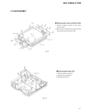
Removing the Case and Panel Units 1. Removing the Amp Unit 1. Remove two screws B and seven screws E and then remove Panel Units. Remove four screws D. 3. Remove eleven screws C. 2. Remove Amp Unit. Fig. 10 21 Fig. 9 - 7.2 DISASSEMBLY GM-X822,X722 - Remove eight screws A and then remove Case. 2.
Removing the Case and Panel Units 1. Removing the Amp Unit 1. Remove two screws B and seven screws E and then remove Panel Units. Remove four screws D. 3. Remove eleven screws C. 2. Remove Amp Unit. Fig. 10 21 Fig. 9 - 7.2 DISASSEMBLY GM-X822,X722 - Remove eight screws A and then remove Case. 2.
Service Manual
Page 23
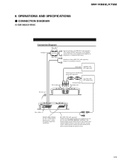
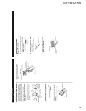
After making all other connections at the amplifier, connect the battery wire terminal of the amplifier to the positive (+) terminal of the car stereo (SYSTEM REMOTE CONTROL). Blue [RD-223] (sold separately). CONNECTION DIAGRAM (1) GM-X822/X1R/UC GM-X822,X722 Connection Diagram Fuse (30 A) Grommet Fuse (30 A) Special red battery wire [RD-223] (sold separately). Connect the male terminal of this wire to metal body or chassis. The female terminal can be connected to the power terminal through the ignition switch. 23 Ground wire (black) [RD-223] (sold...
After making all other connections at the amplifier, connect the battery wire terminal of the amplifier to the positive (+) terminal of the car stereo (SYSTEM REMOTE CONTROL). Blue [RD-223] (sold separately). CONNECTION DIAGRAM (1) GM-X822/X1R/UC GM-X822,X722 Connection Diagram Fuse (30 A) Grommet Fuse (30 A) Special red battery wire [RD-223] (sold separately). Connect the male terminal of this wire to metal body or chassis. The female terminal can be connected to the power terminal through the ignition switch. 23 Ground wire (black) [RD-223] (sold...
Service Manual
Page 24
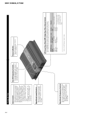
..." when this amplifier is connected to a Pioneer car stereo with the bass boost control. • Bass Boost Level Control and Bass Boost Frequency Control can be output * - 50 to 120 Hz Full range * 50 to 120 Hz - Speaker Type Sub-woofer Full range Full range * See the "Cut Off Frequency Control" section. If the sound level is too low or distorts, adjust the gain control. • Adjust the gain control to 12 dB. Power Indicator The power indicator lights when the power is set to LPF (or HPF...
..." when this amplifier is connected to a Pioneer car stereo with the bass boost control. • Bass Boost Level Control and Bass Boost Frequency Control can be output * - 50 to 120 Hz Full range * 50 to 120 Hz - Speaker Type Sub-woofer Full range Full range * See the "Cut Off Frequency Control" section. If the sound level is too low or distorts, adjust the gain control. • Adjust the gain control to 12 dB. Power Indicator The power indicator lights when the power is set to LPF (or HPF...
Service Manual
Page 25
.... • Use pliers, etc., to crimp lugs to wires. Pass the battery wire from the engine compartment to the interior of the vehicle. • After making all other connections to the amplifier, connect the battery wire terminal of the amplifier to the terminal. • Fix the wires securely with the terminal screws. Twist the battery wire, ground wire and system remote control wire. Attach lugs to wire ends. Terminal screw Speaker output terminal Speaker wire Engine Fuse (30A) compart- Lug Lug Battery wire Ground wire Connecting the Speaker Output Terminals 1. Attach...
.... • Use pliers, etc., to crimp lugs to wires. Pass the battery wire from the engine compartment to the interior of the vehicle. • After making all other connections to the amplifier, connect the battery wire terminal of the amplifier to the terminal. • Fix the wires securely with the terminal screws. Twist the battery wire, ground wire and system remote control wire. Attach lugs to wire ends. Terminal screw Speaker output terminal Speaker wire Engine Fuse (30A) compart- Lug Lug Battery wire Ground wire Connecting the Speaker Output Terminals 1. Attach...
Service Manual
Page 26
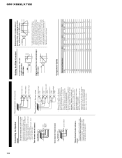
... low-pass filter and high-pass filter for mid-bass/mid): 6 dB/octave L2 C2 0dB -6dB f f CL CL 2 fCH 2f CH • A multi-channel system can be achieved by combining the stereo and mono modes using a combination of filters. The inductance (L) and capacitance (C) will reproduce. GM-X822,X722 26 Connecting the Speaker wires The speaker output mode can be two-channel (stereo), one -channel bridgeable amplifier, but three channels can be set up using inductors...
... low-pass filter and high-pass filter for mid-bass/mid): 6 dB/octave L2 C2 0dB -6dB f f CL CL 2 fCH 2f CH • A multi-channel system can be achieved by combining the stereo and mono modes using a combination of filters. The inductance (L) and capacitance (C) will reproduce. GM-X822,X722 26 Connecting the Speaker wires The speaker output mode can be two-channel (stereo), one -channel bridgeable amplifier, but three channels can be set up using inductors...
Service Manual
Page 27
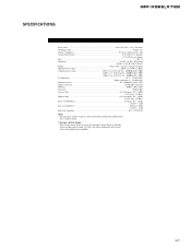
... this unit when an audio signal is input. SPECIFICATIONS GM-X822,X722 Power source ...14.4 V DC (10.8 - 15.1 V allowable) Grounding system ...Negative type Current consumption ...22.5 A (at continuous power, 4 Ω) Average current drawn* ...6.5 A (4 Ω for two channels) 11.3 A (4 Ω for one channel) Fuse ...20 A × 2 Dimensions ...255 (W) × 61 (H) × 260 (D) mm [10 (W) × 2-3/8 (H) × 10-1/4 (D) in.] Weight ...3.4 kg (7.5 lbs.) (Leads for wiring not...
... this unit when an audio signal is input. SPECIFICATIONS GM-X822,X722 Power source ...14.4 V DC (10.8 - 15.1 V allowable) Grounding system ...Negative type Current consumption ...22.5 A (at continuous power, 4 Ω) Average current drawn* ...6.5 A (4 Ω for two channels) 11.3 A (4 Ω for one channel) Fuse ...20 A × 2 Dimensions ...255 (W) × 61 (H) × 260 (D) mm [10 (W) × 2-3/8 (H) × 10-1/4 (D) in.] Weight ...3.4 kg (7.5 lbs.) (Leads for wiring not...


