Owner's Manual
Page 2
... which can radiate radio frequency energy and, if not installed and used in accordance with Part 15 of the following two conditions: (1) this device may invalidate the user's right to Part 15 of the FCC Rules. Section 01 Before you start Thank you read through this manual before using this product. Connect the equipment into an outlet on a circuit different from...
... which can radiate radio frequency energy and, if not installed and used in accordance with Part 15 of the following two conditions: (1) this device may invalidate the user's right to Part 15 of the FCC Rules. Section 01 Before you start Thank you read through this manual before using this product. Connect the equipment into an outlet on a circuit different from...

Owner's Manual
Page 3
... the amplifier and any attached speakers may create a traffic hazard and is illegal in many areas. ESTABLISH A SAFE LEVEL: ! Do not use a fuse of the rating prescribed. Be sure to install the fuse to connect the ground wire first. Doing so could result. En 3 Do not turn up and cause minor burns. the use of headphones may also heat up the volume so high that...
... the amplifier and any attached speakers may create a traffic hazard and is illegal in many areas. ESTABLISH A SAFE LEVEL: ! Do not use a fuse of the rating prescribed. Be sure to install the fuse to connect the ground wire first. Doing so could result. En 3 Do not turn up and cause minor burns. the use of headphones may also heat up the volume so high that...
Owner's Manual
Page 4
.... ! The POWER/PROTECT indicator will turn red and the output will be muted in fire, electric shock or other malfunction. If the speaker output terminal and speaker wire are unable to prevent equipment malfunction. If the subwoofer output terminal and sub- The amplifier will shut down . 4 En Extended use of the car stereo while the en- About the protection function This product has protection function. Doing so may exhaust the battery. Always keep the volume low enough...
.... ! The POWER/PROTECT indicator will turn red and the output will be muted in fire, electric shock or other malfunction. If the speaker output terminal and speaker wire are unable to prevent equipment malfunction. If the subwoofer output terminal and sub- The amplifier will shut down . 4 En Extended use of the car stereo while the en- About the protection function This product has protection function. Doing so may exhaust the battery. Always keep the volume low enough...
Owner's Manual
Page 5
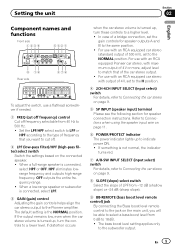
... car stereo volume is turned up, turn these controls to a higher level. ! In case of 500 mV), set to the NORMAL position. When a full-range speaker is connected, select LPF. 3 GAIN (gain) control Adjusting the gain controls helps align the car stereo output to the Pioneer amplifier. HPF eliminates lowrange frequency and outputs high-range frequency. For use with an RCA equipped car stereo (standard output of a bridge connection, set to the H position. 4 2CH-4CH INPUT SELECT (input select) switch For details, refer to Connecting the car stereo on the connected speaker. ! For use...
... car stereo volume is turned up, turn these controls to a higher level. ! In case of 500 mV), set to the NORMAL position. When a full-range speaker is connected, select LPF. 3 GAIN (gain) control Adjusting the gain controls helps align the car stereo output to the Pioneer amplifier. HPF eliminates lowrange frequency and outputs high-range frequency. For use with an RCA equipped car stereo (standard output of a bridge connection, set to the H position. 4 2CH-4CH INPUT SELECT (input select) switch For details, refer to Connecting the car stereo on the connected speaker. ! For use...
Owner's Manual
Page 6
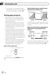
... speakers due to the amplifier, see the Connection diagram on page 7. In such cases, please contact the nearest authorized Pioneer Service Station. Relationship between amplifier gain and head unit output power Setting gain properly ! When outputting high volume sound etc., this unit Preout level: 2 V (Standard: 500 mV) If amplifier gain is raised, the output power will simply increase distortion, with the head unit at high volume using amplifier gain control If the signal waveform is distorted due to control excess output. ! For instruction of this function cuts...
... speakers due to the amplifier, see the Connection diagram on page 7. In such cases, please contact the nearest authorized Pioneer Service Station. Relationship between amplifier gain and head unit output power Setting gain properly ! When outputting high volume sound etc., this unit Preout level: 2 V (Standard: 500 mV) If amplifier gain is raised, the output power will simply increase distortion, with the head unit at high volume using amplifier gain control If the signal waveform is distorted due to control excess output. ! For instruction of this function cuts...

Owner's Manual
Page 7
... j 1 Battery wire (sold separately) a Bass boost level remote control b Bass boost level remote control wire (5 m (16 ft. 5 in.)) c RCA input jack A d RCA input jack B e RCA subwoofer input jack f Front side g Fuse (30 A) × 3 h Speaker/subwoofer output terminals Please see the following section for speaker connection instructions. The maximum length of the wire between the fuse and the positive + terminal of the car stereo. For details, refer to RCA input jack B or RCA subwoofer input jack. 8 Car stereo with RCA output jacks (sold separately) 9 Connecting wire with RCA pin plugs (sold...
... j 1 Battery wire (sold separately) a Bass boost level remote control b Bass boost level remote control wire (5 m (16 ft. 5 in.)) c RCA input jack A d RCA input jack B e RCA subwoofer input jack f Front side g Fuse (30 A) × 3 h Speaker/subwoofer output terminals Please see the following section for speaker connection instructions. The maximum length of the wire between the fuse and the positive + terminal of the car stereo. For details, refer to RCA input jack B or RCA subwoofer input jack. 8 Car stereo with RCA output jacks (sold separately) 9 Connecting wire with RCA pin plugs (sold...
Owner's Manual
Page 8
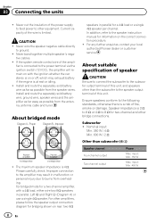
... battery wire as far as possible from the speaker wires. Please carefully check. For bridged mode for a 4 W load or a single 4 W speaker per channel. Ensure speakers conform to the subwoofer output terminal of this unit, and speakers other amplifiers, please follow the speaker output connection diagram for bridging shown on or off, which may result in parallel, Left + and Right * (Diagram A) or use a single 4 W speaker. input: Min. 150 W Max. For other than subwoofer (4 W) Speaker channel Four-channel output Two-channel output Power Max. The maximum speaker...
... battery wire as far as possible from the speaker wires. Please carefully check. For bridged mode for a 4 W load or a single 4 W speaker per channel. Ensure speakers conform to the subwoofer output terminal of this unit, and speakers other amplifiers, please follow the speaker output connection diagram for bridging shown on or off, which may result in parallel, Left + and Right * (Diagram A) or use a single 4 W speaker. input: Min. 150 W Max. For other than subwoofer (4 W) Speaker channel Four-channel output Two-channel output Power Max. The maximum speaker...
Owner's Manual
Page 9
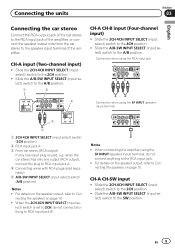
...5 Connection when using the SP INPUT (speaker input) terminal, do not connect anything to RCA input jack A. 4 Connecting wires with RCA plugs (sold separately) 5 A/B-SW INPUT SELECT (input select) switch (A/B position) Notes ! For details on page 10. ! CH-A CH-SW input ! Slide the 2CH-4CH INPUT SELECT (input select) switch to the 2CH position. ! When connecting the amplifier using the SP INPUT (speaker input) terminal 4 3 1 2CH-4CH INPUT SELECT (input select) switch (2CH position) 2 RCA input jack A 3 From car stereo (RCA output) If only one output (RCA output), connect the plug...
...5 Connection when using the SP INPUT (speaker input) terminal, do not connect anything to RCA input jack A. 4 Connecting wires with RCA plugs (sold separately) 5 A/B-SW INPUT SELECT (input select) switch (A/B position) Notes ! For details on page 10. ! CH-A CH-SW input ! Slide the 2CH-4CH INPUT SELECT (input select) switch to the 2CH position. ! When connecting the amplifier using the SP INPUT (speaker input) terminal 4 3 1 2CH-4CH INPUT SELECT (input select) switch (2CH position) 2 RCA input jack A 3 From car stereo (RCA output) If only one output (RCA output), connect the plug...
Owner's Manual
Page 10
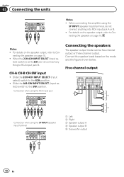
... speaker leads based on the speaker output, refer to RCA input jack B. For details on the mode and the figure shown below. lect) switch is set to 2CH, do not connect anything to Con- Notes ! Slide the A/B-SW INPUT SELECT (input select) switch to the 4CH position. ! When the 2CH-4CH INPUT SELECT (input se- Section 03 Connecting the units Notes ! Connection when using the SP INPUT (speaker input) terminal 1 Left 2 Right 3 Speaker output A 4 Speaker output B 5 Subwoofer output...
... speaker leads based on the speaker output, refer to RCA input jack B. For details on the mode and the figure shown below. lect) switch is set to 2CH, do not connect anything to Con- Notes ! Slide the A/B-SW INPUT SELECT (input select) switch to the 4CH position. ! When the 2CH-4CH INPUT SELECT (input se- Section 03 Connecting the units Notes ! Connection when using the SP INPUT (speaker input) terminal 1 Left 2 Right 3 Speaker output A 4 Speaker output B 5 Subwoofer output...
Owner's Manual
Page 11
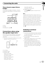
.../black: Rear right * 4 Speaker input wire To the SP INPUT (speaker input) terminal of the twisted wires. ! Do not solder or bind the ends of this unit. Fasten while making sure to not to tighten and loosen the terminal screw of the wire. ! In such cases, please use it must be connected together synchronously, connect the head unit and all amplifiers via the system remote control wire. Connecting the units Section 03 English Three‐channel output (Stereo bridge...
.../black: Rear right * 4 Speaker input wire To the SP INPUT (speaker input) terminal of the twisted wires. ! Do not solder or bind the ends of this unit. Fasten while making sure to not to tighten and loosen the terminal screw of the wire. ! In such cases, please use it must be connected together synchronously, connect the head unit and all amplifiers via the system remote control wire. Connecting the units Section 03 English Three‐channel output (Stereo bridge...
Owner's Manual
Page 12
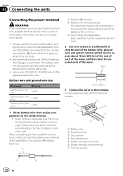
.... Connect the battery wire directly to the car battery positive (+) terminal and the ground wire to short-circuit the wire damaging it , take care not to the car body. ! Fix the wires securely with the terminal screws. 7 6 2 4 1 3 5 1 Battery wire 2 Power terminal 3 Ground wire 4 Ground terminal 5 System remote control wire 6 System remote control terminal 7 Terminal screws 1 3 12 En When drilling a cable pass-hole into the vehicle body and routing a battery wire thorough it by the cut edges or burrs of 8 AWG to 16 AWG wire for the speaker/subwoofer wire. Use a wire of...
.... Connect the battery wire directly to the car battery positive (+) terminal and the ground wire to short-circuit the wire damaging it , take care not to the car body. ! Fix the wires securely with the terminal screws. 7 6 2 4 1 3 5 1 Battery wire 2 Power terminal 3 Ground wire 4 Ground terminal 5 System remote control wire 6 System remote control terminal 7 Terminal screws 1 3 12 En When drilling a cable pass-hole into the vehicle body and routing a battery wire thorough it by the cut edges or burrs of 8 AWG to 16 AWG wire for the speaker/subwoofer wire. Use a wire of...
Owner's Manual
Page 13
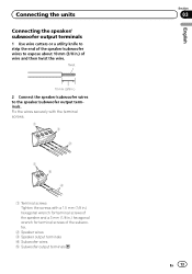
Connecting the units Connecting the speaker/ subwoofer output terminals 1 Use wire cutters or a utility knife to strip the end of the speaker/subwoofer wires to the speaker/subwoofer output terminals. Twist 10 mm (3/8 in.) 2 Connect the speaker/subwoofer wires to expose about 10 mm (3/8 in .) hexagonal wrench for terminal screws of wire and then twist the wire. Fix the wires securely with the terminal screws. 1 3 2 1 5 4 1 Terminal screws Tighten the screws with a 1.5 mm (1/8 in.) hexagonal wrench for terminal screws of the speaker and a 3 mm (1/8 in .) of...
Connecting the units Connecting the speaker/ subwoofer output terminals 1 Use wire cutters or a utility knife to strip the end of the speaker/subwoofer wires to the speaker/subwoofer output terminals. Twist 10 mm (3/8 in.) 2 Connect the speaker/subwoofer wires to expose about 10 mm (3/8 in .) hexagonal wrench for terminal screws of wire and then twist the wire. Fix the wires securely with the terminal screws. 1 3 2 1 5 4 1 Terminal screws Tighten the screws with a 1.5 mm (1/8 in.) hexagonal wrench for terminal screws of the speaker and a 3 mm (1/8 in .) of...
Owner's Manual
Page 14
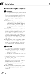
... as on the car model. When drilling to install the amplifier, always confirm no parts are used, they may interfere with a floor mat or carpet. ! CAUTION ! To ensure proper heat dissipation of the driver's seat. ! Place all cables away from damage. To ensure proper installation, use the supplied parts in : - fuel/brake lines, wiring) from hot places, such as short-circuit may result. ! Allow...
... as on the car model. When drilling to install the amplifier, always confirm no parts are used, they may interfere with a floor mat or carpet. ! CAUTION ! To ensure proper heat dissipation of the driver's seat. ! Place all cables away from damage. To ensure proper installation, use the supplied parts in : - fuel/brake lines, wiring) from hot places, such as short-circuit may result. ! Allow...
Owner's Manual
Page 15
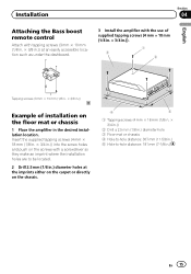
... in.)) into the screw holes and push on the screws with a screwdriver so they make an imprint where the installation holes are to -hole distance: 181 mm (7-1/8 in the desired installation location. Installation Section 04 English Attaching the Bass boost remote control Attach with the use of supplied tapping screws (4 mm × ... in.) diameter holes at an easily accessible location such as under the dashboard. 3 Install the amplifier with tapping screws (3 mm × 10 mm (1/8 in. × 3/8 in.)) at the imprints either on the carpet or directly on the floor mat or chassis 1 Place the...
... in.)) into the screw holes and push on the screws with a screwdriver so they make an imprint where the installation holes are to -hole distance: 181 mm (7-1/8 in the desired installation location. Installation Section 04 English Attaching the Bass boost remote control Attach with the use of supplied tapping screws (4 mm × ... in.) diameter holes at an easily accessible location such as under the dashboard. 3 Install the amplifier with tapping screws (3 mm × 10 mm (1/8 in. × 3/8 in.)) at the imprints either on the carpet or directly on the floor mat or chassis 1 Place the...
Owner's Manual
Page 16
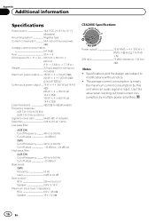
... dB/oct High pass filter: (A/B CH) Cut off frequency 40 Hz to 500 Hz Cut off slope 12 dB/oct Bass boost: (SW) Frequency 50 Hz Level 0 dB to 18 dB Gain control: RCA 200 mV to 6.5 V Speaker 0.8 V to modifications without notice. ! The average current consumption is input. Specifications and the design are subject to 16 V Maximum input level / impedance: RCA 6.5 V / 25 kW Speaker 16 V / 12 kW CEA2006 Specifications Power output 75...
... dB/oct High pass filter: (A/B CH) Cut off frequency 40 Hz to 500 Hz Cut off slope 12 dB/oct Bass boost: (SW) Frequency 50 Hz Level 0 dB to 18 dB Gain control: RCA 200 mV to 6.5 V Speaker 0.8 V to modifications without notice. ! The average current consumption is input. Specifications and the design are subject to 16 V Maximum input level / impedance: RCA 6.5 V / 25 kW Speaker 16 V / 12 kW CEA2006 Specifications Power output 75...

Owner's Manual
Page 53
CH-SW CH-B CH-A INPUT SELECT 4CH-2CH 4CH INPUT SELECT A/B-SW SW RCA 5 2 3 1 2 4 1 1 2 3 A 4 B 5 2 SP INPUT SP INPUT A B RCA 3 1 1 2 3 Ar ٨
CH-SW CH-B CH-A INPUT SELECT 4CH-2CH 4CH INPUT SELECT A/B-SW SW RCA 5 2 3 1 2 4 1 1 2 3 A 4 B 5 2 SP INPUT SP INPUT A B RCA 3 1 1 2 3 Ar ٨

Owner's Manual
Page 54
...; 5 SP INPUT RCA CH-SW CH-A INPUT SELECT 4CH-2CH 2CH INPUT SELECT A/B-SW SW 4CH-2CH INPUT SELECT 2CH B RCA 4 3 1 INPUT SELECT 4CH-2CH 2CH 2 A RCA 3 RCA RCA A RCA 4 RCA 5 INPUT SELECT A/B-SW (A/B...
...; 5 SP INPUT RCA CH-SW CH-A INPUT SELECT 4CH-2CH 2CH INPUT SELECT A/B-SW SW 4CH-2CH INPUT SELECT 2CH B RCA 4 3 1 INPUT SELECT 4CH-2CH 2CH 2 A RCA 3 RCA RCA A RCA 4 RCA 5 INPUT SELECT A/B-SW (A/B...

Owner's Manual
Page 65
...; 1 2 4 1 1 2 3 A 4 B 5 2 CH-SW CH-B CH-A INPUT SELECT 4CH-2CH 4CH INPUT SELECT A/B-SW SW RCA SP INPUT 3 1 1 2 3 SP...
...; 1 2 4 1 1 2 3 A 4 B 5 2 CH-SW CH-B CH-A INPUT SELECT 4CH-2CH 4CH INPUT SELECT A/B-SW SW RCA SP INPUT 3 1 1 2 3 SP...

Owner's Manual
Page 66
...;5 SP INPUT RCA CH-SW CH-A INPUT SELECT 4CH-2CH 2CH INPUT SELECT A/B-SW SW 4 3 1 INPUT SELECT 4CH-2CH 2CH 2 A RCA 3 RCA RCA A RCA 4 RCA 5 INPUT SELECT A/B-SW A/B INPUT SELECT 4CH-2CH 2CH B RCA CH-B CH-A INPUT SELECT 4CH-2CH...
...;5 SP INPUT RCA CH-SW CH-A INPUT SELECT 4CH-2CH 2CH INPUT SELECT A/B-SW SW 4 3 1 INPUT SELECT 4CH-2CH 2CH 2 A RCA 3 RCA RCA A RCA 4 RCA 5 INPUT SELECT A/B-SW A/B INPUT SELECT 4CH-2CH 2CH B RCA CH-B CH-A INPUT SELECT 4CH-2CH...


