Owner's Manual
Page 3
...sound level, set the dial and leave it could result in potentially hazardous situations. ! This unit is recommended. Ensure that the ground wire is properly connected to cause cancer and birth defect or other reproductive harm. En 3 Visit our website http://www.pioneerelectronics.com in recreational...volumes of an improper fuse could result in many areas. Register your hearing "comfort level" adapts to your dealer or nearest authorized Pioneer Service Station. The Safety of Your Ears is illegal in fire, generation of the rating prescribed. Guard against this unit, make ...
...sound level, set the dial and leave it could result in potentially hazardous situations. ! This unit is recommended. Ensure that the ground wire is properly connected to cause cancer and birth defect or other reproductive harm. En 3 Visit our website http://www.pioneerelectronics.com in recreational...volumes of an improper fuse could result in many areas. Register your hearing "comfort level" adapts to your dealer or nearest authorized Pioneer Service Station. The Safety of Your Ears is illegal in fire, generation of the rating prescribed. Guard against this unit, make ...
Owner's Manual
Page 4
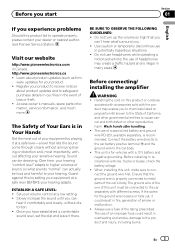
... function. Always disconnect the negative * terminal of electric shock or short circuit during installation. ! If the speaker output terminal and speaker wire are unable to disassemble or modify this number on a surface with liquids. Always keep the volume low enough to protect the product and...or idling may exhaust the battery. ing functions will operate to hear outside sounds. ! Do not use of the separately sold battery wire or the amplifier fuse blows. When this occurs, switch the system power off and the am- Electrical shock could result in your ...
... function. Always disconnect the negative * terminal of electric shock or short circuit during installation. ! If the speaker output terminal and speaker wire are unable to disassemble or modify this number on a surface with liquids. Always keep the volume low enough to protect the product and...or idling may exhaust the battery. ing functions will operate to hear outside sounds. ! Do not use of the separately sold battery wire or the amplifier fuse blows. When this occurs, switch the system power off and the am- Electrical shock could result in your ...
Owner's Manual
Page 7
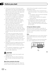
...the car stereo is at rest or idling. tive cables. ! Never shorten any wires, the protection circuit may exhaust battery if the engine is on page 9. 7 RCA input jack 8 System remote control wire (sold se- a Fuse 30 A × 2 (GM-A5602) / 25 A × 1 (GMA3602) b Fuse (30 A) ×... 2 c Grommet d Rear side e Front side 1 Special red battery wire RD-223 (sold separately) After completing all other equipment. sive...
...the car stereo is at rest or idling. tive cables. ! Never shorten any wires, the protection circuit may exhaust battery if the engine is on page 9. 7 RCA input jack 8 System remote control wire (sold se- a Fuse 30 A × 2 (GM-A5602) / 25 A × 1 (GMA3602) b Fuse (30 A) ×... 2 c Grommet d Rear side e Front side 1 Special red battery wire RD-223 (sold separately) After completing all other equipment. sive...
Owner's Manual
Page 8
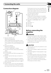
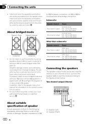
...wire, ground wire, speaker wires and the amplifier as far away as possible from the antenna, antenna cable and tuner. The amplifier surface could also become hot to 8 W for monaural and other bridge connection. For any further enquiries, contact your local authorized Pioneer... sold battery wire as far as possible from the speaker wires. Amplifier damage, smoke, and overheating could result. Subwoofer Speaker channel Two-channel output One-channel output Power Nominal input: Min. 150 W (GM-A5602) Min. 60 W (GM-A3602) Nominal input: Min. 450 W (GM-A5602) Min. 180 W (GM-A3602) !...
...wire, ground wire, speaker wires and the amplifier as far away as possible from the antenna, antenna cable and tuner. The amplifier surface could also become hot to 8 W for monaural and other bridge connection. For any further enquiries, contact your local authorized Pioneer... sold battery wire as far as possible from the speaker wires. Amplifier damage, smoke, and overheating could result. Subwoofer Speaker channel Two-channel output One-channel output Power Nominal input: Min. 150 W (GM-A5602) Min. 60 W (GM-A3602) Nominal input: Min. 450 W (GM-A5602) Min. 180 W (GM-A3602) !...
Owner's Manual
Page 9
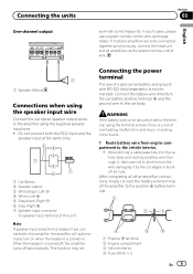
... engine compartment to the amplifier using the terminal screws, there is turned on. Connect the battery wire directly to the car battery positive terminal + and the ground wire to the positive + battery terminal. 1 Positive + terminal 2 Engine compartment 3 Vehicle interior 4 Fuse (30 A) × 2 ... the headunit is recommended. In such cases, please use of overheating, malfunction and injury, including minor burns. 1 Route battery wire from a headunit are to be connected together synchronously, connect the head unit and all other amplifier connections, finally connect the battery...
... engine compartment to the amplifier using the terminal screws, there is turned on. Connect the battery wire directly to the car battery positive terminal + and the ground wire to the positive + battery terminal. 1 Positive + terminal 2 Engine compartment 3 Vehicle interior 4 Fuse (30 A) × 2 ... the headunit is recommended. In such cases, please use of overheating, malfunction and injury, including minor burns. 1 Route battery wire from a headunit are to be connected together synchronously, connect the head unit and all other amplifier connections, finally connect the battery...
Owner's Manual
Page 10
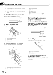
... output terminals. Twist 1 Lug (sold separately) 2 Speaker wire 3 Connect the speaker wires to wire ends. Fix the wires securely with the terminal screws. 1 System remote control terminal 2 Ground terminal 10 En Use pliers, etc., to crimp lugs to wires. 1 Lug (sold separately) 2 Battery wire 3 Ground wire 4 Connect the wires to wire ends. Section 03 Connecting the units 5 Insert the...
... output terminals. Twist 1 Lug (sold separately) 2 Speaker wire 3 Connect the speaker wires to wire ends. Fix the wires securely with the terminal screws. 1 System remote control terminal 2 Ground terminal 10 En Use pliers, etc., to crimp lugs to wires. 1 Lug (sold separately) 2 Battery wire 3 Ground wire 4 Connect the wires to wire ends. Section 03 Connecting the units 5 Insert the...
Owner's Manual
Page 11
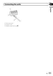
Connecting the units 1 Terminal screws 2 Speaker wires 3 Speaker output terminals English Section 03 En 11
Connecting the units 1 Terminal screws 2 Speaker wires 3 Speaker output terminals English Section 03 En 11
Owner's Manual
Page 12
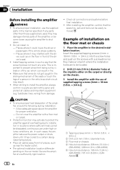
...Drill a 2.5 mm (1/8 in.) diameter hole. 3 Floor mat or chassis 4 Hole-to-hole distance: 338 mm (13-1/4 in.) (GM-A5602) / 228 mm (9 in.) (GM-A3602) 5 Hole-to shut down until it could injure the driver or passengers if the vehicle stops suddenly. - Protection function may interfere ...of the amplifier, or become loose causing the amplifier to -hole distance: 196 mm (7-3/4 in.) (GM-A5602) / 161 mm (6-3/8 in .) diameter holes at a sufficiently rigid location. ! If any wire. To ensure proper installation, use of the amplifier, ensure the following during installation: - This is important...
...Drill a 2.5 mm (1/8 in.) diameter hole. 3 Floor mat or chassis 4 Hole-to-hole distance: 338 mm (13-1/4 in.) (GM-A5602) / 228 mm (9 in.) (GM-A3602) 5 Hole-to shut down until it could injure the driver or passengers if the vehicle stops suddenly. - Protection function may interfere ...of the amplifier, or become loose causing the amplifier to -hole distance: 196 mm (7-3/4 in.) (GM-A5602) / 161 mm (6-3/8 in .) diameter holes at a sufficiently rigid location. ! If any wire. To ensure proper installation, use of the amplifier, ensure the following during installation: - This is important...
Owner's Manual
Page 13
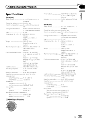
Additional information Appendix English Specifications GM-A5602 Power source 14.4 V DC (10.8 V to 15.1 V allowable) Grounding system Negative type Current consumption 36 A (at continuous power, 4 W) Average current drawn ......... 9.5 A (4 W for... 25 A × 1 Dimensions (W × H × D) ... 238 mm × 60 mm × 180 mm (9-3/8 in. × 2-3/8 in. × 7-1/8 in.) Weight 1.4 kg (3.1 lbs) (Leads for wiring not included) Maximum power output ....... 120 W × 2 (4 W) / 200 W × 2 (2 W) / 400 W TOTAL (BRIDGE) Continuous power output ... 60 W × 2 (at 14.4 V, 4 W, 20 ...
Additional information Appendix English Specifications GM-A5602 Power source 14.4 V DC (10.8 V to 15.1 V allowable) Grounding system Negative type Current consumption 36 A (at continuous power, 4 W) Average current drawn ......... 9.5 A (4 W for... 25 A × 1 Dimensions (W × H × D) ... 238 mm × 60 mm × 180 mm (9-3/8 in. × 2-3/8 in. × 7-1/8 in.) Weight 1.4 kg (3.1 lbs) (Leads for wiring not included) Maximum power output ....... 120 W × 2 (4 W) / 200 W × 2 (2 W) / 400 W TOTAL (BRIDGE) Continuous power output ... 60 W × 2 (at 14.4 V, 4 W, 20 ...


