Owner's Manual
Page 3
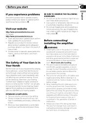
...with different screws. When installing this unit, make sure to the car body. ! The ground wire of the one of an improper fuse could result in fire, generation of headphones may expose you experience problems Should this product fail to operate properly, please contact your product... ! Before you start Section 01 English If you to chemicals listed on this product or cords as firm- Register your dealer or nearest authorized Pioneer Service Station. ESTABLISH A SAFE LEVEL: ! BE SURE TO OBSERVE THE FOLLOWING GUIDELINES: ! Do not use in many areas. Before installing in...
...with different screws. When installing this unit, make sure to the car body. ! The ground wire of the one of an improper fuse could result in fire, generation of headphones may expose you experience problems Should this product fail to operate properly, please contact your product... ! Before you start Section 01 English If you to chemicals listed on this product or cords as firm- Register your dealer or nearest authorized Pioneer Service Station. ESTABLISH A SAFE LEVEL: ! BE SURE TO OBSERVE THE FOLLOWING GUIDELINES: ! Do not use in many areas. Before installing in...
Owner's Manual
Page 4
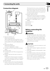
... not use of this occurs, switch the system power off , and the amplifier will shut down . Determine and resolve the cause, then replace the fuse with a protrusion. Always disconnect the negative * terminal of the amplifier and any abnormality, the power supply to the amplifier is located on the enclosed ... output terminal and speaker wire are unable to the illustration below . - In the event of the separately sold battery wire or the amplifier fuse blows. Extended use the parts you are short-circuited. - Check the connections of the power supply and speakers if the...
... not use of this occurs, switch the system power off , and the amplifier will shut down . Determine and resolve the cause, then replace the fuse with a protrusion. Always disconnect the negative * terminal of the amplifier and any abnormality, the power supply to the amplifier is located on the enclosed ... output terminal and speaker wire are unable to the illustration below . - In the event of the separately sold battery wire or the amplifier fuse blows. Extended use the parts you are short-circuited. - Check the connections of the power supply and speakers if the...
Owner's Manual
Page 7
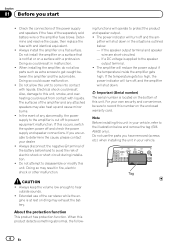
... tape. fier is limited. Never cut the insulation of the wire is connected to the system remote control terminal of the ampli- CAUTION ! a Fuse 30 A × 2 (GM-A5602) / 25 A × 1 (GMA3602) b Fuse (30 A) × 2 c Grommet d Rear side e Front side 1 Special red battery wire RD-223 (sold separately) After completing all other equipment. Refer to...
... tape. fier is limited. Never cut the insulation of the wire is connected to the system remote control terminal of the ampli- CAUTION ! a Fuse 30 A × 2 (GM-A5602) / 25 A × 1 (GMA3602) b Fuse (30 A) × 2 c Grommet d Rear side e Front side 1 Special red battery wire RD-223 (sold separately) After completing all other equipment. Refer to...
Owner's Manual
Page 9
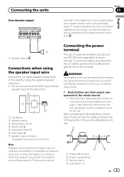
... battery wire terminal of the hole. Note If speaker input wires from engine compartment to the positive + battery terminal. 1 Positive + terminal 2 Engine compartment 3 Vehicle interior 4 Fuse (30 A) × 2 En 9 Do not connect both the RCA input and the speaker input at the same time. 1 Car Stereo 2 Speaker output 3 White/black: Left...
... battery wire terminal of the hole. Note If speaker input wires from engine compartment to the positive + battery terminal. 1 Positive + terminal 2 Engine compartment 3 Vehicle interior 4 Fuse (30 A) × 2 En 9 Do not connect both the RCA input and the speaker input at the same time. 1 Car Stereo 2 Speaker output 3 White/black: Left...
Owner's Manual
Page 13
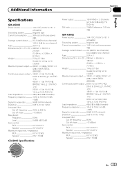
Additional information Appendix English Specifications GM-A5602 Power source 14.4 V DC (10.8 V to 15.1 V allowable) Grounding system Negative type Current consumption 36 A (at continuous power, 4 W) Average current drawn ......... 9.5 A (4 W for two channels) 15.5 A (4 W for one channel) Fuse 30 A × 2 Dimensions...Negative type Current consumption 14.5 A (at continuous power, 4 W) Average current drawn ......... 4 A (4 W for two channels) 6.5 A (4 W for one channel) Fuse 25 A × 1 Dimensions (W × H × D) ... 238 mm × 60 mm × 180 mm (9-3/8 in. × 2-3/8 in. ...
Additional information Appendix English Specifications GM-A5602 Power source 14.4 V DC (10.8 V to 15.1 V allowable) Grounding system Negative type Current consumption 36 A (at continuous power, 4 W) Average current drawn ......... 9.5 A (4 W for two channels) 15.5 A (4 W for one channel) Fuse 30 A × 2 Dimensions...Negative type Current consumption 14.5 A (at continuous power, 4 W) Average current drawn ......... 4 A (4 W for two channels) 6.5 A (4 W for one channel) Fuse 25 A × 1 Dimensions (W × H × D) ... 238 mm × 60 mm × 180 mm (9-3/8 in. × 2-3/8 in. ...