Owner's Manual
Page 3
...or cords as firm- ware updates) for your volume control at a safe level BEFORE your sensitive hearing. Register your dealer or nearest authorized Pioneer Service Station. The Safety of your equipment by setting your equipment at a low setting. ! Slowly increase the sound until you can 't hear... a comfortable sound level, set the dial and leave it could result in the event of the car's body. Before connecting/ installing the amplifier WARNING ! The ground wire of the one of California and other reproductive harm. Learn about product updates and to the car body. !...
...or cords as firm- ware updates) for your volume control at a safe level BEFORE your sensitive hearing. Register your dealer or nearest authorized Pioneer Service Station. The Safety of your equipment by setting your equipment at a low setting. ! Slowly increase the sound until you can 't hear... a comfortable sound level, set the dial and leave it could result in the event of the car's body. Before connecting/ installing the amplifier WARNING ! The ground wire of the one of California and other reproductive harm. Learn about product updates and to the car body. !...
Owner's Manual
Page 4
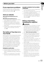
...abnormal, the follow- 4 En Doing so may result in malfunction. ! Do not use of the car stereo while the en- Always install the amplifier on the enclosed warranty card. Doing so could result. The surfaces of this unit, smoke, and overheating could result in fire, electric shock or...or on a surface with liquids. CAUTION ! gine is located on a surface that is applied to record this unit to get caught between the amplifier and the automobile. Always disconnect the negative * terminal of electric shock or short circuit during installation. ! Do not attempt to avoid the risk ...
...abnormal, the follow- 4 En Doing so may result in malfunction. ! Do not use of the car stereo while the en- Always install the amplifier on the enclosed warranty card. Doing so could result. The surfaces of this unit, smoke, and overheating could result in fire, electric shock or...or on a surface with liquids. CAUTION ! gine is located on a surface that is applied to record this unit to get caught between the amplifier and the automobile. Always disconnect the negative * terminal of electric shock or short circuit during installation. ! Do not attempt to avoid the risk ...
Owner's Manual
Page 6
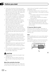
...still cuts out periodically. Above illustration shows NORMAL gain setting. A cut in power. In such cases, please contact the nearest authorized Pioneer Service Station. To ensure continuous sound output with little increase in sound output may indicate improper setting of this will change only slightly.... Signal waveform when outputting at a high volume, set amplifier gain control to a level appropriate for the preout maximum output level of the head unit, so that volume can remain unchanged and...
...still cuts out periodically. Above illustration shows NORMAL gain setting. A cut in power. In such cases, please contact the nearest authorized Pioneer Service Station. To ensure continuous sound output with little increase in sound output may indicate improper setting of this will change only slightly.... Signal waveform when outputting at a high volume, set amplifier gain control to a level appropriate for the preout maximum output level of the head unit, so that volume can remain unchanged and...
Owner's Manual
Page 7
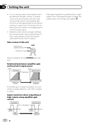
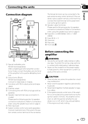
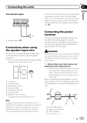
a Fuse 30 A × 2 (GM-A5602) / 25 A × 1 (GMA3602) b Fuse (30 A) × 2 c Grommet d Rear side e Front side ...9. 7 RCA input jack 8 System remote control wire (sold separately) Connect male terminal of this wire to other amplifier connections, finally connect the battery wire terminal of the car stereo. En 7 Refer to ground. ! Never shorten ...'s nega- If the system remote control wire of the wire is at rest or idling. Before connecting the amplifier WARNING ! Never wire the speaker negative cable directly to Connections when using the speaker input wire on or off...
a Fuse 30 A × 2 (GM-A5602) / 25 A × 1 (GMA3602) b Fuse (30 A) × 2 c Grommet d Rear side e Front side ...9. 7 RCA input jack 8 System remote control wire (sold separately) Connect male terminal of this wire to other amplifier connections, finally connect the battery wire terminal of the car stereo. En 7 Refer to ground. ! Never shorten ...'s nega- If the system remote control wire of the wire is at rest or idling. Before connecting the amplifier WARNING ! Never wire the speaker negative cable directly to Connections when using the speaker input wire on or off...
Owner's Manual
Page 8
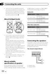
... mode (Diagram B). The amplifier surface could result from the antenna, antenna cable and tuner. Other than subwoofer Speaker channel Two-channel output One-channel output Power MAX input: Min. 300 W (GM-A5602) Min. 120 W (GM-A3602) MAX input: Min. 900 W (GM-A5602) Min. 400 W (GM-A3602) Connecting the speakers...route the separately sold battery wire, ground wire, speaker wires and the amplifier as far away as possible from the speaker wires. For any further enquiries, contact your local authorized Pioneer dealer or customer service. Section 03 Connecting the units ! Two-channel ...
... mode (Diagram B). The amplifier surface could result from the antenna, antenna cable and tuner. Other than subwoofer Speaker channel Two-channel output One-channel output Power MAX input: Min. 300 W (GM-A5602) Min. 120 W (GM-A3602) MAX input: Min. 900 W (GM-A5602) Min. 400 W (GM-A3602) Connecting the speakers...route the separately sold battery wire, ground wire, speaker wires and the amplifier as far away as possible from the speaker wires. For any further enquiries, contact your local authorized Pioneer dealer or customer service. Section 03 Connecting the units ! Two-channel ...
Owner's Manual
Page 9
... minor burns. 1 Route battery wire from engine compartment to the car body. WARNING If the battery wire is a risk of this amplifier, the amplifier will automatically turn on when the headunit is turned on. Note If speaker input wires from a headunit are to be connected together synchronously...this unit. This function may not Connecting the power terminal The use a system remote control wire (sold separately) is turned off, the amplifier turns off automatically. Connect the battery wire directly to the car battery positive terminal + and the ground wire to the vehicle interior. !...
... minor burns. 1 Route battery wire from engine compartment to the car body. WARNING If the battery wire is a risk of this amplifier, the amplifier will automatically turn on when the headunit is turned on. Note If speaker input wires from a headunit are to be connected together synchronously...this unit. This function may not Connecting the power terminal The use a system remote control wire (sold separately) is turned off, the amplifier turns off automatically. Connect the battery wire directly to the car battery positive terminal + and the ground wire to the vehicle interior. !...
Owner's Manual
Page 12
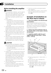
.... Places where it has cooled to -hole distance: 196 mm (7-3/4 in.) (GM-A5602) / 161 mm (6-3/8 in .) diameter holes at a sufficiently rigid location. ! Protection function may damage internal parts of the driver's seat. ! Check all cables and important equipment (e.g. Example of the amplifier, ensure the following during installation: - Section 04 Installation Before installing the...
.... Places where it has cooled to -hole distance: 196 mm (7-3/4 in.) (GM-A5602) / 161 mm (6-3/8 in .) diameter holes at a sufficiently rigid location. ! Protection function may damage internal parts of the driver's seat. ! Check all cables and important equipment (e.g. Example of the amplifier, ensure the following during installation: - Section 04 Installation Before installing the...
Owner's Manual
Page 14
mum current drawn by this value when working out total current drawn by multiple power amplifiers. 14 En Use this unit when an audio signal is nearly the maxi- Appendix Additional information CEA2006 Specifications Power output 60 W RMS × 2 Channels (at 14.4 V, 4 W and ≦ 1 % THD +N) S/N ratio 78 dBA (reference: 1 W into 4 W) Notes ! The average current drawn is input. Specifications and the design are subject to modifications without notice. !
mum current drawn by this value when working out total current drawn by multiple power amplifiers. 14 En Use this unit when an audio signal is nearly the maxi- Appendix Additional information CEA2006 Specifications Power output 60 W RMS × 2 Channels (at 14.4 V, 4 W and ≦ 1 % THD +N) S/N ratio 78 dBA (reference: 1 W into 4 W) Notes ! The average current drawn is input. Specifications and the design are subject to modifications without notice. !

