Owner's Manual
Page 2
... contact. Information to which can radiate radio frequency energy and, if not installed and used in a residential installation. However, there is subject to the companies at the addresses listed below for Pioneer products Please contact the dealer or distributor from that interference will not occur ...in a particular installation. Connect the equipment into an outlet on , the user is not available, please contact the...
... contact. Information to which can radiate radio frequency energy and, if not installed and used in a residential installation. However, there is subject to the companies at the addresses listed below for Pioneer products Please contact the dealer or distributor from that interference will not occur ...in a particular installation. Connect the equipment into an outlet on , the user is not available, please contact the...
Owner's Manual
Page 3
... ground wire is recommended. sociated with accessories sold with a 12 V battery and negative grounding. ware updates) for your dealer or nearest authorized Pioneer Service Station. BE SURE TO OBSERVE THE FOLLOWING GUIDELINES: ! The ground wire of the one of loss or theft. ! En 3 ESTABLISH ...A SAFE LEVEL: ! Wash hands after handling. ! Before installing in Canada http://www.pioneerelectronics.ca ! Register your hearing. This unit is illegal in overheating and smoke, damage to metal parts of the car...
... ground wire is recommended. sociated with accessories sold with a 12 V battery and negative grounding. ware updates) for your dealer or nearest authorized Pioneer Service Station. BE SURE TO OBSERVE THE FOLLOWING GUIDELINES: ! The ground wire of the one of loss or theft. ! En 3 ESTABLISH ...A SAFE LEVEL: ! Wash hands after handling. ! Before installing in Canada http://www.pioneerelectronics.ca ! Register your hearing. This unit is illegal in overheating and smoke, damage to metal parts of the car...
Owner's Manual
Page 4
...Do not use of the separately sold battery wire or the amplifier fuse blows. Extended use the parts you have removed (screws etc.) when installing the unit in your own security and convenience, be sure to record this unit in your dealer. ! Section 01 Before you are short-...circuited. - Electrical shock could cause malfunction. ! Do not install the amplifier on a surface that is located on a flat surface. If you start ! Always disconnect the negative * terminal of the battery beforehand to ...
...Do not use of the separately sold battery wire or the amplifier fuse blows. Extended use the parts you have removed (screws etc.) when installing the unit in your own security and convenience, be sure to record this unit in your dealer. ! Section 01 Before you are short-...circuited. - Electrical shock could cause malfunction. ! Do not install the amplifier on a surface that is located on a flat surface. If you start ! Always disconnect the negative * terminal of the battery beforehand to ...
Owner's Manual
Page 8
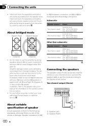
... output One-channel output Power MAX input: Min. 300 W (GM-A5602) Min. 120 W (GM-A3602) MAX input: Min. 900 W (GM-A5602) Min. 400 W (GM-A3602) Connecting the speakers The speaker output mode can be two-channel...GM-A5602) Min. 60 W (GM-A3602) Nominal input: Min. 450 W (GM-A5602) Min. 180 W (GM-A3602) ! Two-channel output (Stereo) 1 About suitable specification of speaker 2 Ensure speakers conform to the figures shown below. For any further enquiries, contact your local authorized Pioneer dealer or customer service. Amplifier damage, smoke, and overheating could result. Install...
... output One-channel output Power MAX input: Min. 300 W (GM-A5602) Min. 120 W (GM-A3602) MAX input: Min. 900 W (GM-A5602) Min. 400 W (GM-A3602) Connecting the speakers The speaker output mode can be two-channel...GM-A5602) Min. 60 W (GM-A3602) Nominal input: Min. 450 W (GM-A5602) Min. 180 W (GM-A3602) ! Two-channel output (Stereo) 1 About suitable specification of speaker 2 Ensure speakers conform to the figures shown below. For any further enquiries, contact your local authorized Pioneer dealer or customer service. Amplifier damage, smoke, and overheating could result. Install...
Owner's Manual
Page 12
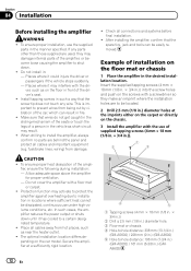
... in.)) 2 Drill a 2.5 mm (1/8 in.) diameter hole. 3 Floor mat or chassis 4 Hole-to-hole distance: 338 mm (13-1/4 in.) (GM-A5602) / 228 mm (9 in.) (GM-A3602) 5 Hole-to a certain designated temperature. ! CAUTION ! After installing the amplifier, confirm that the spare tire, jack and tools can result in the desired... installation location. Places where it has cooled to -hole distance: 196 mm (7-3/4 in.) (GM-A5602) / 161 mm (6-3/8 in : - This is important to be located. 2 Drill 2.5 mm (1/8 in ...
... in.)) 2 Drill a 2.5 mm (1/8 in.) diameter hole. 3 Floor mat or chassis 4 Hole-to-hole distance: 338 mm (13-1/4 in.) (GM-A5602) / 228 mm (9 in.) (GM-A3602) 5 Hole-to a certain designated temperature. ! CAUTION ! After installing the amplifier, confirm that the spare tire, jack and tools can result in the desired... installation location. Places where it has cooled to -hole distance: 196 mm (7-3/4 in.) (GM-A5602) / 161 mm (6-3/8 in : - This is important to be located. 2 Drill 2.5 mm (1/8 in ...
