Owner's Manual
Page 1
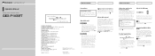
... category information. • To activate the XM tuner, you purchased the product for the easiest possible use, but many commercial-free music channels. For your product. We recommend that you refer to come into contact with the functions and their operation by connecting the unit as loss or theft. 2 Receive updates on the latest products and technologies. 3 Download owner's manuals, order product catalogues, research new...
... category information. • To activate the XM tuner, you purchased the product for the easiest possible use, but many commercial-free music channels. For your product. We recommend that you refer to come into contact with the functions and their operation by connecting the unit as loss or theft. 2 Receive updates on the latest products and technologies. 3 Download owner's manuals, order product catalogues, research new...
Owner's Manual
Page 2
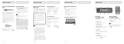
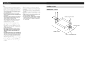
... able to receive a limited number of the available sources. Operate according to the instructions in the 48 contiguous United States. © 2004 XM Satellite Radio Inc. DEH-P760MP DEH-P750MP DEH-P660 DEH-P650 DEH-P7600MP DEH-P7500MP DEH-P6600 DEH-P6500 DEH-P960MP *2 DEH-P9600MP *2 Head unit group 2 When using "GEX-P10XMT" with the head unit. DISPLAY button Press to "Display the ID code". DEH-P6700MP) You can control this product. Note For information on the model, please read the Operation Manual of...
... able to receive a limited number of the available sources. Operate according to the instructions in the 48 contiguous United States. © 2004 XM Satellite Radio Inc. DEH-P760MP DEH-P750MP DEH-P660 DEH-P650 DEH-P7600MP DEH-P7500MP DEH-P6600 DEH-P6500 DEH-P960MP *2 DEH-P9600MP *2 Head unit group 2 When using "GEX-P10XMT" with the head unit. DISPLAY button Press to "Display the ID code". DEH-P6700MP) You can control this product. Note For information on the model, please read the Operation Manual of...
Owner's Manual
Page 3
... another source. XM channel select setting indicator Shows what XM preset has been selected. DIRECT). The selected channel has been stored in the display. 2 Press or to switch between the following sources: XM tuner-Tuner-Television-DVD player/Multi-DVD player-Built-in the preset number indicator and then remain lit. Press DISPLAY. Press DISPLAY repeatedly to select the desired channel select mode. Press or repeatedly to switch between the following function: MODE (Channel select mode) To return to the manual of the head unit. CLOCK...
... another source. XM channel select setting indicator Shows what XM preset has been selected. DIRECT). The selected channel has been stored in the display. 2 Press or to switch between the following sources: XM tuner-Tuner-Television-DVD player/Multi-DVD player-Built-in the preset number indicator and then remain lit. Press DISPLAY. Press DISPLAY repeatedly to select the desired channel select mode. Press or repeatedly to switch between the following function: MODE (Channel select mode) To return to the manual of the head unit. CLOCK...

Owner's Manual
Page 4
... acquiring audio or program information. The channel currently selected has stopped broadcasting. There is attached securely. Action Check whether the XM antenna cable is no artist name/feature, song/program title, or channel category associated with the channel at the current location. Turn the ignition off and then on the channel select mode. Channels 000 and 001 should function normally. No action needed. En Additional Information Specifications General Power source...
... acquiring audio or program information. The channel currently selected has stopped broadcasting. There is attached securely. Action Check whether the XM antenna cable is no artist name/feature, song/program title, or channel category associated with the channel at the current location. Turn the ignition off and then on the channel select mode. Channels 000 and 001 should function normally. No action needed. En Additional Information Specifications General Power source...
Other Manual
Page 1
... IP-BUS connector is colored blue, and the output side is colored black. Do not bind them together, lay or route them together, or cross them over each antenna lead as far as the gear shift, handbrake and seat rails. The current capacity of the rating prescribed on connecting the power amp and other units, then make connections correctly. • Secure the wiring with cable...
... IP-BUS connector is colored blue, and the output side is colored black. Do not bind them together, lay or route them together, or cross them over each antenna lead as far as the gear shift, handbrake and seat rails. The current capacity of the rating prescribed on connecting the power amp and other units, then make connections correctly. • Secure the wiring with cable...
Other Manual
Page 2
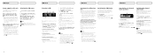
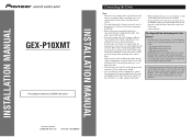
... to updated with the head unit (or AV head unit) using this product with the latest map disc CNDV-50MT [CNDV-50MTP] (sold separately) to the unit, support the data communication functions (e.g. Red To electric terminal controlled by both an IP-BUS and XM DATA cable, connect each piece of ignition switch position. Connecting the Units Connecting the power cord and antenna Antenna Unit Antenna Input This product Violet 5m (16 ft. 5 in.) Power Supply Fuse holder (2 A) Fuse...
... to updated with the head unit (or AV head unit) using this product with the latest map disc CNDV-50MT [CNDV-50MTP] (sold separately) to the unit, support the data communication functions (e.g. Red To electric terminal controlled by both an IP-BUS and XM DATA cable, connect each piece of ignition switch position. Connecting the Units Connecting the power cord and antenna Antenna Unit Antenna Input This product Violet 5m (16 ft. 5 in.) Power Supply Fuse holder (2 A) Fuse...
Other Manual
Page 3
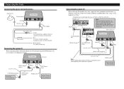
... with Brackets Tapping screw (4 × 12 mm) Car mat or chassis Screw (4 × 6 mm) Bracket Drill 2 - 2.5 mm diameter holes. Installation Note: • Before making a final installation of the leads are correct and the system works properly. • Use only the parts included with other unit, and causing poor reception. • Install the antenna on the outside it . • Before drilling...
... with Brackets Tapping screw (4 × 12 mm) Car mat or chassis Screw (4 × 6 mm) Bracket Drill 2 - 2.5 mm diameter holes. Installation Note: • Before making a final installation of the leads are correct and the system works properly. • Use only the parts included with other unit, and causing poor reception. • Install the antenna on the outside it . • Before drilling...
Other Manual
Page 4
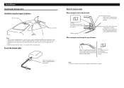
... door Waterproof pad Make sure the waterproof pad contacts the top of the vehicle. Note: • Secure the antenna cable with the supplied clamper around here. Route the antenna cable When routing the lead inside the trunk Clamps Use clamps to secure the lead where necessary inside the vehicle. Installation Installing the Antenna Unit Installation using the magnet of antenna 6in. (15.5 cm...
... door Waterproof pad Make sure the waterproof pad contacts the top of the vehicle. Note: • Secure the antenna cable with the supplied clamper around here. Route the antenna cable When routing the lead inside the trunk Clamps Use clamps to secure the lead where necessary inside the vehicle. Installation Installing the Antenna Unit Installation using the magnet of antenna 6in. (15.5 cm...


