Operation Manual
Page 1
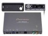
... Pioneer Corporation. Universal XM satellite digital tuner system Operation Manual GEX-FM903XM PIONEER CORPORATION 4-1, MEGURO 1-CHOME, MEGURO-KU, TOKYO 153-8654, JAPAN PIONEER ELECTRONICS (USA) INC. Printed in front of the Deafness Research Foundation. To establish a safe level: • Start your musical enjoyment. Sound can hear it comfortably and clearly, and without annoying blaring or distortion - P.O. Copyright © 2001 by playing it 's time...
... Pioneer Corporation. Universal XM satellite digital tuner system Operation Manual GEX-FM903XM PIONEER CORPORATION 4-1, MEGURO 1-CHOME, MEGURO-KU, TOKYO 153-8654, JAPAN PIONEER ELECTRONICS (USA) INC. Printed in front of the Deafness Research Foundation. To establish a safe level: • Start your musical enjoyment. Sound can hear it comfortably and clearly, and without annoying blaring or distortion - P.O. Copyright © 2001 by playing it 's time...
Operation Manual
Page 2
... commercial-free music channels. IP-BUS MODE When combining with a PIONEER Head Unit featuring an IP-BUS input: • Audio is protected by other than an authorized service facility could void authorization to "Display the ID Code". Coast-tocoast coverage. Plus the best sports, comedy, talk, news and entertainment, including USA Today, Discovery Radio, NASCAR, Sesame Workshop, CNNfn and CNN/SI. How to the installation manual for repair without activation...
... commercial-free music channels. IP-BUS MODE When combining with a PIONEER Head Unit featuring an IP-BUS input: • Audio is protected by other than an authorized service facility could void authorization to "Display the ID Code". Coast-tocoast coverage. Plus the best sports, comedy, talk, news and entertainment, including USA Today, Discovery Radio, NASCAR, Sesame Workshop, CNNfn and CNN/SI. How to the installation manual for repair without activation...
Operation Manual
Page 3
... your car stereo and tune to set in "FM Modulator Setting". 2. Press button 4.) Hold for the first time, refer to "FM Modulator Setting" to the frequency set the FM frequency and volume appropriately. 1. Select a desired Channel. Refer to "FM Modulator Setting", and change the Source to an FM source on your desired Channel. • You can select a desired Channel by Channel Number". 4. Basic Operation (ADD-ON MODE) Key Finder Control Unit 5/∞/2/3 buttons DISPLAY button MODE button POWER button Buttons 1-6 BAND button Basic Operation of your car radio. •...
... your car stereo and tune to set in "FM Modulator Setting". 2. Press button 4.) Hold for the first time, refer to "FM Modulator Setting" to the frequency set the FM frequency and volume appropriately. 1. Select a desired Channel. Refer to "FM Modulator Setting", and change the Source to an FM source on your desired Channel. • You can select a desired Channel by Channel Number". 4. Basic Operation (ADD-ON MODE) Key Finder Control Unit 5/∞/2/3 buttons DISPLAY button MODE button POWER button Buttons 1-6 BAND button Basic Operation of your car radio. •...
Operation Manual
Page 4
... XM antenna cable is identified with the 5/∞ buttons. XM programing also carries song or program title, artist name, and other . Select the desired Channel Category with a unique Radio ID. Wait until encryption code is selected. Select the Channel Category Select mode. (Refer to enter the FM Modulator Setting mode. 2. You will need the Radio ID when activating XM service or when reporting a problem. Using the XM tuner (ADD-ON MODE) Switching the Display XM Channels each channel...
... XM antenna cable is identified with the 5/∞ buttons. XM programing also carries song or program title, artist name, and other . Select the desired Channel Category with a unique Radio ID. Wait until encryption code is selected. Select the Channel Category Select mode. (Refer to enter the FM Modulator Setting mode. 2. You will need the Radio ID when activating XM service or when reporting a problem. Using the XM tuner (ADD-ON MODE) Switching the Display XM Channels each channel...
Operation Manual
Page 5
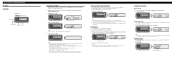
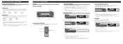
... units. Note: • When using a remote controller, you can increase/decrease Channel Number by Channel Number When Channel Number Select mode is selected. • Select a desired Channel. DEH-P6300) 5/∞/2/3 buttons Buttons 1-6 SOURCE button FUNCTION button BAND button Remote Controller (e.g. For details, refer to store that has been moved to store in the Head Unit's Operation Manual. Note: • When two external units are connected, the allocation of Head Unit. Select XM. EQ SOURCE DISP 1 2 3 4 5 6 Each press changes the Source ... 2. SELECT...
... units. Note: • When using a remote controller, you can increase/decrease Channel Number by Channel Number When Channel Number Select mode is selected. • Select a desired Channel. DEH-P6300) 5/∞/2/3 buttons Buttons 1-6 SOURCE button FUNCTION button BAND button Remote Controller (e.g. For details, refer to store that has been moved to store in the Head Unit's Operation Manual. Note: • When two external units are connected, the allocation of Head Unit. Select XM. EQ SOURCE DISP 1 2 3 4 5 6 Each press changes the Source ... 2. SELECT...
Operation Manual
Page 6
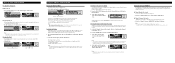
... need the Radio ID when activating XM service or when reporting a problem. Note: • If you select another Channel, display of the ID Code is provided as a Channel Category for 2 seconds and the unit returns to memorize more Channels, they are organized into various program categories, e.g. Basic Operation (IP-BUS MODE) Recalling Preset Channels 7 Direct Recall • Press a button from a Channel Category when you select a channel. SELECT SFEQ 3 4 5 6 E B FUNC AUDIO Each press changes the Band ... Initially, Channel Number Select mode...
... need the Radio ID when activating XM service or when reporting a problem. Note: • If you select another Channel, display of the ID Code is provided as a Channel Category for 2 seconds and the unit returns to memorize more Channels, they are organized into various program categories, e.g. Basic Operation (IP-BUS MODE) Recalling Preset Channels 7 Direct Recall • Press a button from a Channel Category when you select a channel. SELECT SFEQ 3 4 5 6 E B FUNC AUDIO Each press changes the Band ... Initially, Channel Number Select mode...
Installation Manual
Page 1
... through a hole into the lead. Do not route wiring in the electrical system, be sure to use only fuse of the rating prescribed on connecting the power amp and other units, then make connections correctly. • Secure the wiring with cable clamps or adhesive tape. The current capacity of the IP-BUS connector is blue, and the output side is black. Printed in a vehicle that...
... through a hole into the lead. Do not route wiring in the electrical system, be sure to use only fuse of the rating prescribed on connecting the power amp and other units, then make connections correctly. • Secure the wiring with cable clamps or adhesive tape. The current capacity of the IP-BUS connector is blue, and the output side is black. Printed in a vehicle that...
Installation Manual
Page 2
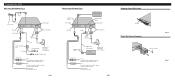
... the Control Unit's Cable Clamper Fig. 4 Protect the Antenna Connector Screw (3 × 6 mm) Fig. 5 Red To electric terminal controlled by ignition switch (12 V DC) ON/OFF. Connecting the Units When using IP-BUS mode (Fig. 3) IP-BUS Input (Blue) Power Supply Multi-CD player (sold separately) IP-BUS Output (Black) Antenna Input This Unit Black Green (Terrestrial) Yellow (Satellite) To IP-BUS Input (Blue) IP-BUS cable (sold separately) Head Unit (sold separately) Antenna Unit (AN-90XM) (sold separately) To FM car radio Fuse holder Fuse resistor...
... the Control Unit's Cable Clamper Fig. 4 Protect the Antenna Connector Screw (3 × 6 mm) Fig. 5 Red To electric terminal controlled by ignition switch (12 V DC) ON/OFF. Connecting the Units When using IP-BUS mode (Fig. 3) IP-BUS Input (Blue) Power Supply Multi-CD player (sold separately) IP-BUS Output (Black) Antenna Input This Unit Black Green (Terrestrial) Yellow (Satellite) To IP-BUS Input (Blue) IP-BUS cable (sold separately) Head Unit (sold separately) Antenna Unit (AN-90XM) (sold separately) To FM car radio Fuse holder Fuse resistor...
Installation Manual
Page 3
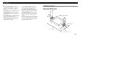
... finally installing the unit, connect the wiring temporarily, making sure it . • Before drilling any mounting holes always check behind where you want to drill the holes. Route all leads and cords carefully around the sliding mechanism so they do not get in the driver's way...free while the car is moving, and cause injury or an accident. • If this unit is all connected up properly, and the unit and the system work properly. • Use only the parts included with the unit to 2.5 mm diameter holes. Installing the Tuner Unit Mounting with your nearest dealer if installation...
... finally installing the unit, connect the wiring temporarily, making sure it . • Before drilling any mounting holes always check behind where you want to drill the holes. Route all leads and cords carefully around the sliding mechanism so they do not get in the driver's way...free while the car is moving, and cause injury or an accident. • If this unit is all connected up properly, and the unit and the system work properly. • Use only the parts included with the unit to 2.5 mm diameter holes. Installing the Tuner Unit Mounting with your nearest dealer if installation...
Installation Manual
Page 4
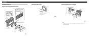
... very dangerous if the cord gets tangled in the steering wheel, so install the cord so that comes with a flatbladed screwdriver, and secure the bracket in place. 44 - 46 mm Dashboard Flush mounting bracket Removing the control unit (Fig. 8) Insert the release plate that it cannot get in the illustration. Installation Installing the Control Unit Installation using the flush mounting bracket (Fig. 7) 124 - 126...
... very dangerous if the cord gets tangled in the steering wheel, so install the cord so that comes with a flatbladed screwdriver, and secure the bracket in place. 44 - 46 mm Dashboard Flush mounting bracket Removing the control unit (Fig. 8) Insert the release plate that it cannot get in the illustration. Installation Installing the Control Unit Installation using the flush mounting bracket (Fig. 7) 124 - 126...


