
Owner's Manual
Page 1
DJ MIXER DJM-707 Operating Instructions 1
DJ MIXER DJM-707 Operating Instructions 1
Owner's Manual
Page 2
K015 En NOTE: THE NO USER-SERVICEABLE PARTS COMPARTMENT WARNING IS LOCATED ON THE APPLIANCE BOTTOM. 2 After you have finished reading the instructions, put them away in the explanatory drawings. However the method of the power plug and power outlet may sometimes differ from that shown in a safe place for buying this Pioneer product. Thank you for future reference. Please read through these operating instructions so you will know how to operate your model properly. In some countries or regions, the shape of connecting and operating the unit is the same.
K015 En NOTE: THE NO USER-SERVICEABLE PARTS COMPARTMENT WARNING IS LOCATED ON THE APPLIANCE BOTTOM. 2 After you have finished reading the instructions, put them away in the explanatory drawings. However the method of the power plug and power outlet may sometimes differ from that shown in a safe place for buying this Pioneer product. Thank you for future reference. Please read through these operating instructions so you will know how to operate your model properly. In some countries or regions, the shape of connecting and operating the unit is the same.

Owner's Manual
Page 3
IMPORTANT NOTICE The serial number for this equipment is for your enclosed warranty card and keep it in a secure area. Please write this product or cords associated with accessories sold with the product will expose you to lead, a chemical known to the State of California and other governmental entities to cause cancer and birth defects or other reproductive harm. Wash hands after handling. 3 WARNING: Handling the cord on this serial number on the bottom plate. This is located on your security.
IMPORTANT NOTICE The serial number for this equipment is for your enclosed warranty card and keep it in a secure area. Please write this product or cords associated with accessories sold with the product will expose you to lead, a chemical known to the State of California and other governmental entities to cause cancer and birth defects or other reproductive harm. Wash hands after handling. 3 WARNING: Handling the cord on this serial number on the bottom plate. This is located on your security.
Owner's Manual
Page 4
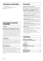
... cross fader operation. 2 Independent cross fader lag cut when performing scratch play . 2 "Fader reverse" function allows reversing of the directions of fader operation movement. 3 Delicate 33-step channel fader curve settings. 4 Can be connected in series to other equipment to provide the shortest-possible signal paths, thus realizing true club sound with a dry cloth. FEATURES 1) Designed for high sound quality Electronic parts have been carefully selected and internal circuitry...
... cross fader operation. 2 Independent cross fader lag cut when performing scratch play . 2 "Fader reverse" function allows reversing of the directions of fader operation movement. 3 Delicate 33-step channel fader curve settings. 4 Can be connected in series to other equipment to provide the shortest-possible signal paths, thus realizing true club sound with a dry cloth. FEATURES 1) Designed for high sound quality Electronic parts have been carefully selected and internal circuitry...
Owner's Manual
Page 5
... DJ mixer. MIC 3 The MIC jack on this DJ mixer supports use of a MM cartridge. 5 When connecting a cassette deck or other mixer outputs to these jacks, set the CH-2 PHONO/LINE selector switch to [LINE]. * The PHONO input for fader start play and back cue. This mixer is not furnished with the CD player should be operated to control operation of the DJ mixer, and connect the AUDIO OUT connectors from the outlet. when performing connections, use the appropriate audio cables to connect...
... DJ mixer. MIC 3 The MIC jack on this DJ mixer supports use of a MM cartridge. 5 When connecting a cassette deck or other mixer outputs to these jacks, set the CH-2 PHONO/LINE selector switch to [LINE]. * The PHONO input for fader start play and back cue. This mixer is not furnished with the CD player should be operated to control operation of the DJ mixer, and connect the AUDIO OUT connectors from the outlet. when performing connections, use the appropriate audio cables to connect...

Owner's Manual
Page 6
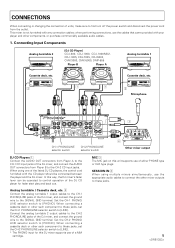
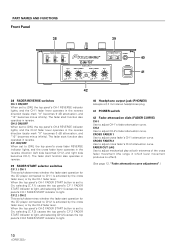
...monitor level dial, regardless of the setting of an amplifier. Connecting Headphones (front panel) Headphones FADER REVERSE CH-1 C.F. Master output MASTER 1 7 XLR type balanced output. 6 MASTER 2 8 RCA type unbalanced output. BOOTH/SESSION OUT 9 These jacks are provided for booth monitor) CH-2 R CD R MASTER 2 L PHONO / LINE LR PHONO SEND RETURN CH-1 LR L R L (MONO) MASTER 1 3 COLD 1 GND CD (MONO) PHONO / LINE PHONO BOOTH/ SESSION OUT SIGNAL GND LINE CH-2 PLAYER CONTROL R 2 HOT SIGNAL LINE GND L CH-1 PLAYER CONTROL MIC R L SESSION IN 7 R L p Power cord...
...monitor level dial, regardless of the setting of an amplifier. Connecting Headphones (front panel) Headphones FADER REVERSE CH-1 C.F. Master output MASTER 1 7 XLR type balanced output. 6 MASTER 2 8 RCA type unbalanced output. BOOTH/SESSION OUT 9 These jacks are provided for booth monitor) CH-2 R CD R MASTER 2 L PHONO / LINE LR PHONO SEND RETURN CH-1 LR L R L (MONO) MASTER 1 3 COLD 1 GND CD (MONO) PHONO / LINE PHONO BOOTH/ SESSION OUT SIGNAL GND LINE CH-2 PLAYER CONTROL R 2 HOT SIGNAL LINE GND L CH-1 PLAYER CONTROL MIC R L SESSION IN 7 R L p Power cord...
Owner's Manual
Page 7
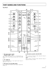
... input jacks, and send them to the TRIM control. 2 CH-1 TRIM dial Use to adjust the CH-1 input signal level (range of adjustment: 10 kHz, ±12 dB). PART NAMES AND FUNCTIONS Top Panel 21 20 10 11 3 4 5 6 7 8 9 21 22 MIC LEVEL - 0 HI -12 +12 LOW -12 +12 MIC SEND SESSION IN - 0 CH-1 SEND FADER START 23 24 25 CH-1 FADER START 26 27 C.F.1 FADER START PHONO 1 /LINE 1 CD 1 PHONO 2 /LINE 2 CD 2 TRIM - +9 HI PROFESSIONAL 2CHANNEL MIXER DJM-707 POWER TRIM...
... input jacks, and send them to the TRIM control. 2 CH-1 TRIM dial Use to adjust the CH-1 input signal level (range of adjustment: 10 kHz, ±12 dB). PART NAMES AND FUNCTIONS Top Panel 21 20 10 11 3 4 5 6 7 8 9 21 22 MIC LEVEL - 0 HI -12 +12 LOW -12 +12 MIC SEND SESSION IN - 0 CH-1 SEND FADER START 23 24 25 CH-1 FADER START 26 27 C.F.1 FADER START PHONO 1 /LINE 1 CD 1 PHONO 2 /LINE 2 CD 2 TRIM - +9 HI PROFESSIONAL 2CHANNEL MIXER DJM-707 POWER TRIM...

Owner's Manual
Page 8
... produces balanced output of adjustment: +9 dB to [MASTER]. LOW Use to adjust CH-1 input bass response (range of adjustment: 70 Hz, +6 dB to -26 dB). 6 MIC SEND button and indicator When set to On, the indicator lights, and microphone signals are output at the SEND jacks. 7 Session input level dial (SESSION IN) Use to adjust the session input volume (range of the front panel's FADER START selector switch; Whether the operation is initiated by operation of the CH-1 fader lever, or...
... produces balanced output of adjustment: +9 dB to [MASTER]. LOW Use to adjust CH-1 input bass response (range of adjustment: 70 Hz, +6 dB to -26 dB). 6 MIC SEND button and indicator When set to On, the indicator lights, and microphone signals are output at the SEND jacks. 7 Session input level dial (SESSION IN) Use to adjust the session input volume (range of the front panel's FADER START selector switch; Whether the operation is initiated by operation of the CH-1 fader lever, or...
Owner's Manual
Page 9
... (Mute). PART NAMES AND FUNCTIONS 34 MASTER LEVEL display button and indicator When depressed to the right side, CH-2 is at maximum output and CH-1 is maximum at scale mark "10," and minimum at minimum. When turned Off, the level meters display the peak levels for CH-1 and CH-2 by the lighting of the top panel's CH-2 FADER START indicator or C.F.2 FADER START indicator. * For DJ CD players supporting the fader start and...
... (Mute). PART NAMES AND FUNCTIONS 34 MASTER LEVEL display button and indicator When depressed to the right side, CH-2 is at maximum output and CH-1 is maximum at scale mark "10," and minimum at minimum. When turned Off, the level meters display the peak levels for CH-1 and CH-2 by the lighting of the top panel's CH-2 FADER START indicator or C.F.2 FADER START indicator. * For DJ CD players supporting the fader start and...
Owner's Manual
Page 10
... 2CHANNEL MIXER DJM-707 FADER CURVE CROSS FADER 1 CROSS FADER 2 FADER CUT LAG MIN MAX FADER START C.F. 1 CH-1 C.F. 2 CH-2 PHONES CH-2 POWER 40 41 42 38 FADER REVERSE switches CH-1 ON/OFF When set to On, selecting [C.F.2] causes the top panel's C.F.2 FADER START indicator to light, and selecting [CH-2] causes the top panel's CH-2 FADER START indicator to light. 40 Headphone output jack (PHONES) Accepts a 6.3 mm stereo headphones plug. 41 POWER switch 42 Fader attenuation dials (FADER CURVE) CH-1 Use to adjust cross fader...
... 2CHANNEL MIXER DJM-707 FADER CURVE CROSS FADER 1 CROSS FADER 2 FADER CUT LAG MIN MAX FADER START C.F. 1 CH-1 C.F. 2 CH-2 PHONES CH-2 POWER 40 41 42 38 FADER REVERSE switches CH-1 ON/OFF When set to On, selecting [C.F.2] causes the top panel's C.F.2 FADER START indicator to light, and selecting [CH-2] causes the top panel's CH-2 FADER START indicator to light. 40 Headphone output jack (PHONES) Accepts a 6.3 mm stereo headphones plug. 41 POWER switch 42 Fader attenuation dials (FADER CURVE) CH-1 Use to adjust cross fader...
Owner's Manual
Page 11
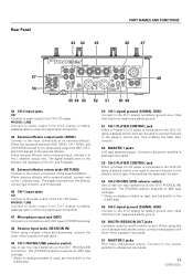
... player. When using an effector with monaural output, connect only to the L channel input. Connect to the power amplifier's balanced input jacks. 53 CH-2 PLAYER CONTROL jack When a Pioneer DJ CD player is connected to the CH-1 CD jacks, a special control cord can be input to both L and R channels. 46 CH-1 input jacks CD Connect to the audio output of the CH-1 CD player. Rear Panel 43 44 45 PART NAMES AND FUNCTIONS 46 47 57 56 CH-2 R CD R MASTER 2 L PHONO / LINE LR PHONO SEND...
... player. When using an effector with monaural output, connect only to the L channel input. Connect to the power amplifier's balanced input jacks. 53 CH-2 PLAYER CONTROL jack When a Pioneer DJ CD player is connected to the CH-1 CD jacks, a special control cord can be input to both L and R channels. 46 CH-1 input jacks CD Connect to the audio output of the CH-1 CD player. Rear Panel 43 44 45 PART NAMES AND FUNCTIONS 46 47 57 56 CH-2 R CD R MASTER 2 L PHONO / LINE LR PHONO SEND...
Owner's Manual
Page 12
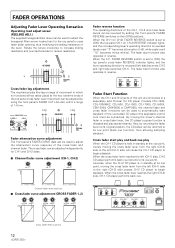
... Channel fader lever positions 7 Cross fader curve adjustment (CROSS FADER 1, 2) LEVEL Fader reverse function The operating directions of the CH-1, CH-2 and cross fader levers can be returned to its cue point). Cross fader start playback of the connected CD player (the applicable control cord must be connected). CH-2 ON ON ON OFF OFF OFF CH-1 PROFESSIONAL 2CHANNEL MIXER DJM-707 FADER CURVE CROSS FADER 1 CROSS FADER 2 FADER CUT LAG MIN MAX FADER START C.F. 1 CH-1 C.F. 2 CH-2 PHONES CH-2 POWER...
... Channel fader lever positions 7 Cross fader curve adjustment (CROSS FADER 1, 2) LEVEL Fader reverse function The operating directions of the CH-1, CH-2 and cross fader levers can be returned to its cue point). Cross fader start playback of the connected CD player (the applicable control cord must be connected). CH-2 ON ON ON OFF OFF OFF CH-1 PROFESSIONAL 2CHANNEL MIXER DJM-707 FADER CURVE CROSS FADER 1 CROSS FADER 2 FADER CUT LAG MIN MAX FADER START C.F. 1 CH-1 C.F. 2 CH-2 PHONES CH-2 POWER...
Owner's Manual
Page 13
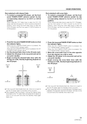
... panel FADER START selector switch for the corresponding channel to its [C.F.1] or [C.F.2] position. FADER START C.F. 1 CH-1 C.F. 2 CH-2 FADER OPERATIONS Start playback with cross fader 1 To control a connected CD player, set the front panel FADER START selector switch for the corresponding channel to its cue point and set for cue point standby. 5 Begin moving the cross fader lever with the timing you wish, thereby beginning playback on the CD player. When the CH-1 FADER START button is pressed, the C.F.2 FADER START indicator lights...
... panel FADER START selector switch for the corresponding channel to its [C.F.1] or [C.F.2] position. FADER START C.F. 1 CH-1 C.F. 2 CH-2 FADER OPERATIONS Start playback with cross fader 1 To control a connected CD player, set the front panel FADER START selector switch for the corresponding channel to its cue point and set for cue point standby. 5 Begin moving the cross fader lever with the timing you wish, thereby beginning playback on the CD player. When the CH-1 FADER START button is pressed, the C.F.2 FADER START indicator lights...
Owner's Manual
Page 14
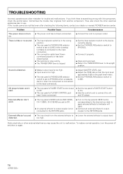
...; Master output level is too high. ÷ Input level is too high. ÷ The rear panel's PHONO/LINE selector switch is set to [PHONO] when a cassette deck or other line component is not connected to the RETURN jacks. ÷ Turn on the top panel's SEND button corresponding to the channel you think there is set to Off. ÷ The rear panel's PLAYER CONTROL jack hasn't been connected. ÷ Set the top panel's FADER START button to On. ÷ Use the control cord to...
...; Master output level is too high. ÷ Input level is too high. ÷ The rear panel's PHONO/LINE selector switch is set to [PHONO] when a cassette deck or other line component is not connected to the RETURN jacks. ÷ Turn on the top panel's SEND button corresponding to the channel you think there is set to Off. ÷ The rear panel's PLAYER CONTROL jack hasn't been connected. ÷ Set the top panel's FADER START button to On. ÷ Use the control cord to...
Owner's Manual
Page 15
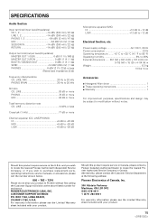
... Channel equalizer (CD, LINE/PHONO) HI 6 dB to -26 dB MID 6 dB to -26 dB LOW 6 dB to -26 dB Microphone equalizer (MIC) HI 12 dB to -12 dB LOW 12 dB to Pioneer without notice. and you wish to locate the nearest Pioneer Authorized Independent Service Company, or if you wish to purchase replacement parts, operating instructions, service manuals, or accessories, please call the number...
... Channel equalizer (CD, LINE/PHONO) HI 6 dB to -26 dB MID 6 dB to -26 dB LOW 6 dB to -26 dB Microphone equalizer (MIC) HI 12 dB to -12 dB LOW 12 dB to Pioneer without notice. and you wish to locate the nearest Pioneer Authorized Independent Service Company, or if you wish to purchase replacement parts, operating instructions, service manuals, or accessories, please call the number...
Owner's Manual
Page 16
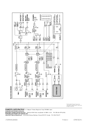
.../ SESSION OUT CH-2 SEND B A H.P. Industrial Products Department: 300 Allstate Parkway, Markham, Ontario L3R OP2, Canada TEL: 905-479-4411 BLOCK DIAGRAM MIC MIC LEVEL 2-BAND EQ. MASTER H.P. TEL: 800-444-OPTI (6784) PIONEER ELECTRONICS OF CANADA, INC. CH-2 CH-2 LEVEL CH-1 LEVEL CH-2 LEVEL MASTER LEVEL METER CH-1, CH-2 MASTER LEVEL(L/R) L 14 9 5 3 1 0 -1 -3 -6 -9 - 15 - 22 dB CH-1 R 14 9 5 3 1 0 -1 -3 -6 -9 - 15 - 22 dB CH-2 VOLTAGE CONTROL VCA CONTROL SIGNAL FADER CURVE CH-1, CH...
.../ SESSION OUT CH-2 SEND B A H.P. Industrial Products Department: 300 Allstate Parkway, Markham, Ontario L3R OP2, Canada TEL: 905-479-4411 BLOCK DIAGRAM MIC MIC LEVEL 2-BAND EQ. MASTER H.P. TEL: 800-444-OPTI (6784) PIONEER ELECTRONICS OF CANADA, INC. CH-2 CH-2 LEVEL CH-1 LEVEL CH-2 LEVEL MASTER LEVEL METER CH-1, CH-2 MASTER LEVEL(L/R) L 14 9 5 3 1 0 -1 -3 -6 -9 - 15 - 22 dB CH-1 R 14 9 5 3 1 0 -1 -3 -6 -9 - 15 - 22 dB CH-2 VOLTAGE CONTROL VCA CONTROL SIGNAL FADER CURVE CH-1, CH...


