Owner's Manual
Page 3
... 4 CAUTIONS REGARDING HANDLING 4 Location 4 Cleaning the Unit 4 FEATURES 4 CONNECTIONS 5 CONNECTION PANEL 5 CONNECTING INPUTS 6 CONNECTING EXTERNAL EFFECTORS, OUTPUT CONNECTORS 7 ABOUT MIDI CONNECTORS 8 CONNECTING MICROPHONE AND HEADPHONES 8 CONNECTING THE POWER CORD 8 NAMES AND FUNCTIONS OF PARTS 9 MIXER OPERATIONS 13... FREQUENCY FILTER OPERATION 19 EFFECT PARAMETERS 20 MIDI SETTINGS 21 SYNCHRONIZING AUDIO SIGNALS TO EXTERNAL SEQUENCER, OR USING DJM-700-S/DJM-700-K INFORMATION TO OPERATE AN EXTERNAL SEQUENCER 21 MIDI MESSAGES 22 PROGRAM CHANGE 24 SNAPSHOT 24 MIDI ON/OFF...
... 4 CAUTIONS REGARDING HANDLING 4 Location 4 Cleaning the Unit 4 FEATURES 4 CONNECTIONS 5 CONNECTION PANEL 5 CONNECTING INPUTS 6 CONNECTING EXTERNAL EFFECTORS, OUTPUT CONNECTORS 7 ABOUT MIDI CONNECTORS 8 CONNECTING MICROPHONE AND HEADPHONES 8 CONNECTING THE POWER CORD 8 NAMES AND FUNCTIONS OF PARTS 9 MIXER OPERATIONS 13... FREQUENCY FILTER OPERATION 19 EFFECT PARAMETERS 20 MIDI SETTINGS 21 SYNCHRONIZING AUDIO SIGNALS TO EXTERNAL SEQUENCER, OR USING DJM-700-S/DJM-700-K INFORMATION TO OPERATE AN EXTERNAL SEQUENCER 21 MIDI MESSAGES 22 PROGRAM CHANGE 24 SNAPSHOT 24 MIDI ON/OFF...
Owner's Manual
Page 4
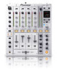
...conventional effecters that carry on other occasions when high sound fidelity is required. (Only linear PCM is used to connect the unit to a Pioneer DJ CD player, thus allowing playback to be exposed to the entire frequency range. Cleaning the Unit • Use a polishing cloth ...8226; "Cross fader assignment" function allows each channel's input to be output in linkage to oily smoke, steam or heat.) • When the unit is supported.) MIDI OUT Virtually all the dial and switch information of the DJM-700-S/ DJM-700-K can be controlled via a 24-bit high quality A/D converter. ...
...conventional effecters that carry on other occasions when high sound fidelity is required. (Only linear PCM is used to connect the unit to a Pioneer DJ CD player, thus allowing playback to be exposed to the entire frequency range. Cleaning the Unit • Use a polishing cloth ...8226; "Cross fader assignment" function allows each channel's input to be output in linkage to oily smoke, steam or heat.) • When the unit is supported.) MIDI OUT Virtually all the dial and switch information of the DJM-700-S/ DJM-700-K can be controlled via a 24-bit high quality A/D converter. ...
Owner's Manual
Page 5
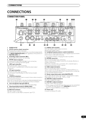
Use to connect to the output connectors of a Pioneer DJ CD player. When the L channel only is connected, the L channel input is output. 15 Master output attenuator switch (MASTER ATT) Use to connect a DJ CD player or other MIDI component (see P. 21). 15 14 ... RETURN R L(MONO) DIGITAL OUT fs(Hz) 48k 96k MIDI OUT 18 17 16 1 POWER switch 2 BOOTH monitor output connectors RCA-type booth monitor output jack. When the connectors are connected, the DJM-700-S/DJM-700-K's fader can be used to perform start/stop on the DJ CD player. 8 Two microphone input jacks (MIC 2) ...
Use to connect to the output connectors of a Pioneer DJ CD player. When the L channel only is connected, the L channel input is output. 15 Master output attenuator switch (MASTER ATT) Use to connect a DJ CD player or other MIDI component (see P. 21). 15 14 ... RETURN R L(MONO) DIGITAL OUT fs(Hz) 48k 96k MIDI OUT 18 17 16 1 POWER switch 2 BOOTH monitor output connectors RCA-type booth monitor output jack. When the connectors are connected, the DJM-700-S/DJM-700-K's fader can be used to perform start/stop on the DJ CD player. 8 Two microphone input jacks (MIC 2) ...
Owner's Manual
Page 6
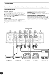
Analog turntable To connect an analog turntable, connect the turntable's audio output cable to one of the DJM-700-S/DJM-700-K's LINE input connectors (channel 1, 3, or 4) or to the CD input connectors (channel 1 or 2), and set the input selector switch to [CD] or [LINE]. ...turntable Analog turntable DJ CD player DJ CD player Cassette deck, etc. 6 En CONNECTING INPUTS Pioneer DJ CD players The audio output connectors of the channel 2 to [LINE]. Connect the ground wire from its audio output connectors to one of a DJ-type CD player can be connected to the CD input connectors...
Analog turntable To connect an analog turntable, connect the turntable's audio output cable to one of the DJM-700-S/DJM-700-K's LINE input connectors (channel 1, 3, or 4) or to the CD input connectors (channel 1 or 2), and set the input selector switch to [CD] or [LINE]. ...turntable Analog turntable DJ CD player DJ CD player Cassette deck, etc. 6 En CONNECTING INPUTS Pioneer DJ CD players The audio output connectors of the channel 2 to [LINE]. Connect the ground wire from its audio output connectors to one of a DJ-type CD player can be connected to the CD input connectors...
Owner's Manual
Page 7
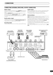
...this way, the mixed L+R audio signal will be sent to [MONO], the master output will be set the effect selector to the output connectors of the master output level setting. If the effector has only monaural output, connect to both L and R channels. Power amplifier (for recording, supporting RCA ... unit is furnished with Ø6.3 mm phone plugs to connect the DJ mixer's RETURN connectors to [SND/ RTN]. Recording output These are output connectors for booth monitor) Cassette deck (analog input recording device) Power amplifier (RCA plug input connectors) Digital input AV amplifier...
...this way, the mixed L+R audio signal will be sent to [MONO], the master output will be set the effect selector to the output connectors of the master output level setting. If the effector has only monaural output, connect to both L and R channels. Power amplifier (for recording, supporting RCA ... unit is furnished with Ø6.3 mm phone plugs to connect the DJ mixer's RETURN connectors to [SND/ RTN]. Recording output These are output connectors for booth monitor) Cassette deck (analog input recording device) Power amplifier (RCA plug input connectors) Digital input AV amplifier...
Owner's Manual
Page 9
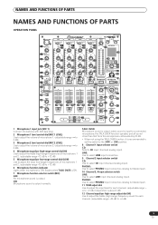
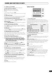
...CD input (line level analog input). flashes when TALK OVER is ON. 7 Microphone function selector switch (MIC) OFF: No microphone sound is output normally. TALK OVER: Microphone sound is ON; NAMES AND FUNCTIONS OF PARTS NAMES AND FUNCTIONS OF PARTS OPERATION PANEL MIC1 CH-1 CD LINE ... (low-range) frequencies of microphones 1 and 2. (adjustable range -12 dB to +12 dB) 6 Microphone function indicator Lights when microphone is output; when sound is input to a connected microphone, the TALK OVER function operates and all sound other than that from the microphone is attenuated by ...
...CD input (line level analog input). flashes when TALK OVER is ON. 7 Microphone function selector switch (MIC) OFF: No microphone sound is output normally. TALK OVER: Microphone sound is ON; NAMES AND FUNCTIONS OF PARTS NAMES AND FUNCTIONS OF PARTS OPERATION PANEL MIC1 CH-1 CD LINE ... (low-range) frequencies of microphones 1 and 2. (adjustable range -12 dB to +12 dB) 6 Microphone function indicator Lights when microphone is output; when sound is input to a connected microphone, the TALK OVER function operates and all sound other than that from the microphone is attenuated by ...
Owner's Manual
Page 10
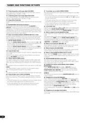
... the signals from microphone 1 and microphone 2 (if the effect selector is set to the [MONO] position, master output, booth monitor output, recording output, digital output are all produced in accordance with the channel fader curve selected with the CH FADER curve switch. 19 CROSS FADER ASSIGN...2, 3, 4 or EFFECTS) button is selected, the selected audio is also added). 24 Master level indicator (MASTER L, R) These segment indicators display the output level from the R channel. In the middle position, the audio from channels set to ON. This setting is applied equally to channels 1 to 4....
... the signals from microphone 1 and microphone 2 (if the effect selector is set to the [MONO] position, master output, booth monitor output, recording output, digital output are all produced in accordance with the channel fader curve selected with the CH FADER curve switch. 19 CROSS FADER ASSIGN...2, 3, 4 or EFFECTS) button is selected, the selected audio is also added). 24 Master level indicator (MASTER L, R) These segment indicators display the output level from the R channel. In the middle position, the audio from channels set to ON. This setting is applied equally to channels 1 to 4....
Owner's Manual
Page 11
... the following section for two seconds, after which effects are used for functions other than setting the beat. 33 MIDI ON/OFF button Sets MIDI output function (not including timing lock) to ON/OFF. BPM counter display (3 digits): In AUTO mode, displays the automatically detected BPM value. When ...the parameter range, the current number will flash but will be set to OFF. 34 MIDI start At MIDI stop button (MIDI START/STOP) Outputs START/STOP signal for adjustments other than time parameters.) • If the TIME dial is first turned ON, automatically defaults to effect OFF, ...
... the following section for two seconds, after which effects are used for functions other than setting the beat. 33 MIDI ON/OFF button Sets MIDI output function (not including timing lock) to ON/OFF. BPM counter display (3 digits): In AUTO mode, displays the automatically detected BPM value. When ...the parameter range, the current number will flash but will be set to OFF. 34 MIDI start At MIDI stop button (MIDI START/STOP) Outputs START/STOP signal for adjustments other than time parameters.) • If the TIME dial is first turned ON, automatically defaults to effect OFF, ...
Owner's Manual
Page 13
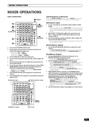
...other than the microphone are attenuated by 20 dB. 2 Use the MIC 1 LEVEL dial to adjust the sound volume of the MASTER LEVEL dial. [Headphones Output] 1 Use the HEADPHONES CUE buttons (channels 1 to 4, MASTER, EFFECTS) to select the source. • The selected HEADPHONES CUE button lights brightly. ... Set the headphones (MONO SPLIT/STEREO) switch. • When HEADPHONES CUE (1, 2, 3, 4 or EFFECTS) button is selected, the selected audio is output to the L channel. Headphones output MONO/ STEREO Fader curve 13 En CH2: Set to [CD] or [LINE]. CH3/4: Set to [LINE] or [PHONO]. 3 Use the TRIM ...
...other than the microphone are attenuated by 20 dB. 2 Use the MIC 1 LEVEL dial to adjust the sound volume of the MASTER LEVEL dial. [Headphones Output] 1 Use the HEADPHONES CUE buttons (channels 1 to 4, MASTER, EFFECTS) to select the source. • The selected HEADPHONES CUE button lights brightly. ... Set the headphones (MONO SPLIT/STEREO) switch. • When HEADPHONES CUE (1, 2, 3, 4 or EFFECTS) button is selected, the selected audio is output to the L channel. Headphones output MONO/ STEREO Fader curve 13 En CH2: Set to [CD] or [LINE]. CH3/4: Set to [LINE] or [PHONO]. 3 Use the TRIM ...
Owner's Manual
Page 19
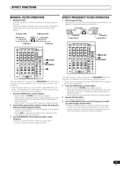
... to adjust the filter's cutoff frequency. • Rotate counterclockwise to apply a low-pass filter. • Rotate clockwise to the FREQUENCY dial. The output sounds of the manual effecter become the input sounds for the manual effecter. 1 Press the FILTER button so that it flashes. • Confirm that ...dial to a desired frequency band alone. High-frequency sounds are set to ROLL, REVERSE ROLL, UP ROLL, or DOWN ROLL, the beat effect's output sound becomes the input sound for the beat effect. • When the beat effect type is first turned ON, defaults to steadily lighted. 2 ...
... to adjust the filter's cutoff frequency. • Rotate counterclockwise to apply a low-pass filter. • Rotate clockwise to the FREQUENCY dial. The output sounds of the manual effecter become the input sounds for the manual effecter. 1 Press the FILTER button so that it flashes. • Confirm that ...dial to a desired frequency band alone. High-frequency sounds are set to ROLL, REVERSE ROLL, UP ROLL, or DOWN ROLL, the beat effect's output sound becomes the input sound for the beat effect. • When the beat effect type is first turned ON, defaults to steadily lighted. 2 ...

Owner's Manual
Page 20
... selector is set to [CF.A], [CF.B], or [MASTER], even if the effect monitor is turned ON, if the selected channel's sound is not output to the master output, the effect sound will not be heard. (*2) When effect is disabled (OFF), the effect sound will not be heard, even if monitor is set... sound. Amount of BPM time. Sets cut time of 1/16 to 16/1 per 1 beat of BPM. 1 to +100 %. 9 CRUSH Cycle of crush effect movement is output. relative of 1 beat of BPM time. Amount of BPM. to 4 000 (ms) 12 UP ROLL (*2) Effect time is set in units of 1/4 to 64/1 relative...
... selector is set to [CF.A], [CF.B], or [MASTER], even if the effect monitor is turned ON, if the selected channel's sound is not output to the master output, the effect sound will not be heard. (*2) When effect is disabled (OFF), the effect sound will not be heard, even if monitor is set... sound. Amount of BPM time. Sets cut time of 1/16 to 16/1 per 1 beat of BPM. 1 to +100 %. 9 CRUSH Cycle of crush effect movement is output. relative of 1 beat of BPM time. Amount of BPM. to 4 000 (ms) 12 UP ROLL (*2) Effect time is set in units of 1/4 to 64/1 relative...
Owner's Manual
Page 21
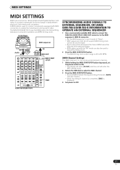
... AUDIO SIGNALS TO EXTERNAL SEQUENCER, OR USING DJM-700-S/DJM-700-K INFORMATION TO OPERATE AN EXTERNAL SEQUENCER 1 Use a commercially available MIDI cable to connect the DJM-700-S/DJM-700-K's MIDI OUT connector to the MIDI sequencer's...output range is an acronym for "Musical Instrument Digital Interface" and refers to a protocol developed for transmitting data about component operation and BPM (timing clock). A MIDI cable is displayed. 4 Set power to enable the transmission and receipt of data between electronic instruments and computers. DJM-700-S/DJM-700-K 21 En The DJM-700-S/DJM-700...
... AUDIO SIGNALS TO EXTERNAL SEQUENCER, OR USING DJM-700-S/DJM-700-K INFORMATION TO OPERATE AN EXTERNAL SEQUENCER 1 Use a commercially available MIDI cable to connect the DJM-700-S/DJM-700-K's MIDI OUT connector to the MIDI sequencer's...output range is an acronym for "Musical Instrument Digital Interface" and refers to a protocol developed for transmitting data about component operation and BPM (timing clock). A MIDI cable is displayed. 4 Set power to enable the transmission and receipt of data between electronic instruments and computers. DJM-700-S/DJM-700-K 21 En The DJM-700-S/DJM-700...
Owner's Manual
Page 25
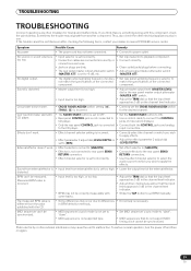
...channel level indicator. • Strike the TAP button to malfunction. TROUBLESHOOTING TROUBLESHOOTING Incorrect operations are dirty. • The rear panel master output attenuator switch (MASTER ATT) is too high, or too low. • BPM may not be rectified even after checking the following ...items, contact your dealer or nearest PIONEER service center. Cross fader doesn't work . • Effect channel selecter setting is incorrect. • Effect parameter 2 adjust dial (LEVEL/DEPTH)...
...channel level indicator. • Strike the TAP button to malfunction. TROUBLESHOOTING TROUBLESHOOTING Incorrect operations are dirty. • The rear panel master output attenuator switch (MASTER ATT) is too high, or too low. • BPM may not be rectified even after checking the following ...items, contact your dealer or nearest PIONEER service center. Cross fader doesn't work . • Effect channel selecter setting is incorrect. • Effect parameter 2 adjust dial (LEVEL/DEPTH)...

Owner's Manual
Page 26
...sheet included with your product. 26 En Alternatively, please contact the Customer Service Department at the above listed number for assistance. PIONEER ELECTRONICS (USA), INC. SPECIFICATIONS SPECIFICATIONS 1 General Power source AC 120 V, 60 Hz Power consumption 34 W Operating temperature . ...output connector Stereo phone jack (Ø6.3 mm 1 CONTROL connector Mini phone jacks (Ø3.5 mm 2 4 Accessories Operating Instructions 1 Warranty card 1 Specifications and appearance are subject to change without first calling the Customer Support Division at the following address: Pioneer...
...sheet included with your product. 26 En Alternatively, please contact the Customer Service Department at the above listed number for assistance. PIONEER ELECTRONICS (USA), INC. SPECIFICATIONS SPECIFICATIONS 1 General Power source AC 120 V, 60 Hz Power consumption 34 W Operating temperature . ...output connector Stereo phone jack (Ø6.3 mm 1 CONTROL connector Mini phone jacks (Ø3.5 mm 2 4 Accessories Operating Instructions 1 Warranty card 1 Specifications and appearance are subject to change without first calling the Customer Support Division at the following address: Pioneer...
