Owner's Manual
Page 2
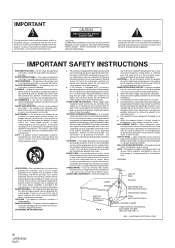
... never be blocked or covered. NONUSE PERIODS - POWER-CORD PROTECTION - POWER LINES - OVERLOADING - Refer all servicing to the presence of any service or repairs to determine that produce heat. HEAT - TORS (NEC SECTION 810-21) GROUND CLAMPS POWER SERVICE GROUNDING ELECTRODE SYSTEM (NEC ART 250, PART H) NEC - The safety and operating instructions should still fail to fit, contact your electrician to replace your obsolete...
... never be blocked or covered. NONUSE PERIODS - POWER-CORD PROTECTION - POWER LINES - OVERLOADING - Refer all servicing to the presence of any service or repairs to determine that produce heat. HEAT - TORS (NEC SECTION 810-21) GROUND CLAMPS POWER SERVICE GROUNDING ELECTRODE SYSTEM (NEC ART 250, PART H) NEC - The safety and operating instructions should still fail to fit, contact your electrician to replace your obsolete...
Owner's Manual
Page 3
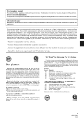
... the instructions, may invalidate the user's right to which can radiate radio frequency energy and, if not installed and used in accordance with the limits for a Class B digital device, pursuant to do this manufacturer and the Electronic Industries Association's Consumer Electronics Group recommend you can maximize the fun and excitement your volume control at a safe level BEFORE your new sound...
... the instructions, may invalidate the user's right to which can radiate radio frequency energy and, if not installed and used in accordance with the limits for a Class B digital device, pursuant to do this manufacturer and the Electronic Industries Association's Consumer Electronics Group recommend you can maximize the fun and excitement your volume control at a safe level BEFORE your new sound...
Owner's Manual
Page 8
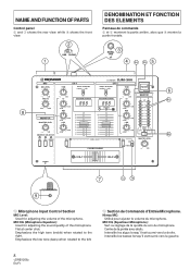
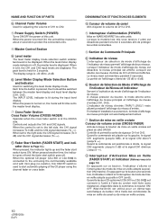
... PARTS Control panel 2 and 3 shows the rear view, while 9 shows the front view. 2 LINE PHONO 1 DENOMINATION ET FONCTION DES ELEMENTS Panneau de commande 2 et 3 montrent la partie arrière, alors que 9 montre la partie frontale. 3 SIGNAL GND 4 5 4A 4B MIC MIC LEVEL TRIM CH-1 INPUT SELECTOR PHONO 1 / LINE 1 DJ MIXER DJM-300 CH-2 INPUT SELECTOR PHONO 2 / LINE 2 TRIM POWER -∞ 0dB MIC EQ -∞ 0dB HI CD 1 AUTO BPM...
... PARTS Control panel 2 and 3 shows the rear view, while 9 shows the front view. 2 LINE PHONO 1 DENOMINATION ET FONCTION DES ELEMENTS Panneau de commande 2 et 3 montrent la partie arrière, alors que 9 montre la partie frontale. 3 SIGNAL GND 4 5 4A 4B MIC MIC LEVEL TRIM CH-1 INPUT SELECTOR PHONO 1 / LINE 1 DJ MIXER DJM-300 CH-2 INPUT SELECTOR PHONO 2 / LINE 2 TRIM POWER -∞ 0dB MIC EQ -∞ 0dB HI CD 1 AUTO BPM...
Owner's Manual
Page 10
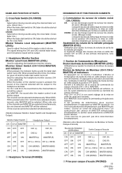
When the level meter display mode indicator is off and the fader start switch turns ON. Each time the button is pressed, the mode will first be set to the master level display. 7 Cross Fader Section Cross Fader Volume (CROSS FADER) Operates when the cross fader switch is -20 dB to +6 dB. 6B Level Meter Display Mode Selection Button and Indicator Used for 2 seconds. Controls and outputs the CH1 and CH2 signals. When set to the left side, the CH1 signal increases (To 0 dB...
When the level meter display mode indicator is off and the fader start switch turns ON. Each time the button is pressed, the mode will first be set to the master level display. 7 Cross Fader Section Cross Fader Volume (CROSS FADER) Operates when the cross fader switch is -20 dB to +6 dB. 6B Level Meter Display Mode Selection Button and Indicator Used for 2 seconds. Controls and outputs the CH1 and CH2 signals. When set to the left side, the CH1 signal increases (To 0 dB...
Owner's Manual
Page 11
The signal mixing the CH1 and CH2 channel fader levels and microphone inputs will be output. 8 Headphone Monitor Section Monitor Level Knob (MONITOR LEVEL) Used for selecting the headphone monitor sources (CH1, CH-2, MASTER). When pressed another time, the indicator goes off and the fader start switch turns ON. For MASTER, the sound after the master control is set will be output to adjust the level of the channels and MASTER are selected simultaneously, only MASTER will be output. CROSS : en cas de mixage à partir...
The signal mixing the CH1 and CH2 channel fader levels and microphone inputs will be output. 8 Headphone Monitor Section Monitor Level Knob (MONITOR LEVEL) Used for selecting the headphone monitor sources (CH1, CH-2, MASTER). When pressed another time, the indicator goes off and the fader start switch turns ON. For MASTER, the sound after the master control is set will be output to adjust the level of the channels and MASTER are selected simultaneously, only MASTER will be output. CROSS : en cas de mixage à partir...

Owner's Manual
Page 12
... button. • Each time the button is pressed, the display mode and indicator lit switch as done previously but also visually, thereby enabling songs with the ear as follows. 3 REAL 3 AVERAGE off . acapella, ad lib, etc.).) (Example) Displays the BPM of the song input to CH1 and CH2. 1 Rotate the TRIM control and adjust the input level so that the display lights up without the input level meter...
... button. • Each time the button is pressed, the display mode and indicator lit switch as done previously but also visually, thereby enabling songs with the ear as follows. 3 REAL 3 AVERAGE off . acapella, ad lib, etc.).) (Example) Displays the BPM of the song input to CH1 and CH2. 1 Rotate the TRIM control and adjust the input level so that the display lights up without the input level meter...

Owner's Manual
Page 13
AUTO BPM COUNTER AUTO BPM COUNTER REAL AVERAGE 2 Goes off S'arrête 13 En/Fr Display when BPM of CH1 (126) and BPM of CH1 and CH2 (Eg. Affichage lorsque le BPM du CH1 (126) et le BPM du CH2 (126) s'accordent. UTILISATION DE LA FONCTION D'EFFET 3 Régler le tempo de lecture (la vitesse) en utilisant le lecteur CH1 et CH2 (Lecteur CD par exemple). CD player). USING THE EFFECT FUNCTION 3 Adjust the play tempo (speed) using the player of CH2 (126) match.
AUTO BPM COUNTER AUTO BPM COUNTER REAL AVERAGE 2 Goes off S'arrête 13 En/Fr Display when BPM of CH1 (126) and BPM of CH1 and CH2 (Eg. Affichage lorsque le BPM du CH1 (126) et le BPM du CH2 (126) s'accordent. UTILISATION DE LA FONCTION D'EFFET 3 Régler le tempo de lecture (la vitesse) en utilisant le lecteur CH1 et CH2 (Lecteur CD par exemple). CD player). USING THE EFFECT FUNCTION 3 Adjust the play tempo (speed) using the player of CH2 (126) match.
Owner's Manual
Page 14
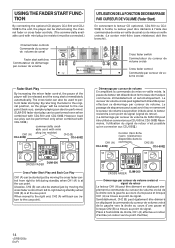
... point de signal. USING THE FADER START FUNCTION UTILISATION DE LA FONCTION DE DEMARRAGE PAR CURSEUR DE VOLUME (Fader Start) By connecting the optional CD players CDJ-500 and CDJ500 to the unit, the player can be started just by moving the cross fader control from right to the cue point). CH2 (B) CDJ-500 CROSS FADER DJM-300 Cross Fader Start Play and Back Cue Play CH1 (A) can be started just by moving the cross fader control from...
... point de signal. USING THE FADER START FUNCTION UTILISATION DE LA FONCTION DE DEMARRAGE PAR CURSEUR DE VOLUME (Fader Start) By connecting the optional CD players CDJ-500 and CDJ500 to the unit, the player can be started just by moving the cross fader control from right to the cue point). CH2 (B) CDJ-500 CROSS FADER DJM-300 Cross Fader Start Play and Back Cue Play CH1 (A) can be started just by moving the cross fader control from...
Owner's Manual
Page 16
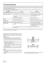
... your nearest PIONEER authorized service center or your dealer to the power outlet. Noises • The input level is off and then on . • The power cord is dirty. • Clean and connect. does not start. • The player control terminal at the rear is not fully inserted, the unit will not work . mercially available cord with the trim knob. To restore normal operation, turn on again. Sometimes...
... your nearest PIONEER authorized service center or your dealer to the power outlet. Noises • The input level is off and then on . • The power cord is dirty. • Clean and connect. does not start. • The player control terminal at the rear is not fully inserted, the unit will not work . mercially available cord with the trim knob. To restore normal operation, turn on again. Sometimes...
Owner's Manual
Page 18
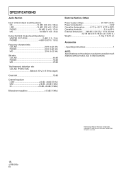
Copyright © 1996 Pioneer Electronic Corporation. All rights reserved. SPECIFICATIONS Audio Section Input terminal (Input level/impedance) CD 14 dBV (200 mV) / 22 kΩ LINE 14 dBV (200 mV) / 47 kΩ PHONO 54 dBV (2 mV) / 47 kΩ MIC 60 dBV (1 mV) / 3 kΩ Output terminal (Output level/impedance) MASTER OUT (RCA 0 dBV (1 V) / 1 kΩ PHONES 4 dBV (0.63 V) / 150 Ω Frequency characteristics CD/LINE 20 Hz to...
Copyright © 1996 Pioneer Electronic Corporation. All rights reserved. SPECIFICATIONS Audio Section Input terminal (Input level/impedance) CD 14 dBV (200 mV) / 22 kΩ LINE 14 dBV (200 mV) / 47 kΩ PHONO 54 dBV (2 mV) / 47 kΩ MIC 60 dBV (1 mV) / 3 kΩ Output terminal (Output level/impedance) MASTER OUT (RCA 0 dBV (1 V) / 1 kΩ PHONES 4 dBV (0.63 V) / 150 Ω Frequency characteristics CD/LINE 20 Hz to...
Owner's Manual
Page 20
..., INC. and you wish to locate the nearest Pioneer Authorized Independent Service Company, or if you wish to purchase replacement parts, operating instructions, service manuals, or accessories, please call the number shown below. 8 0 0 - 8 7 2 - 4 1 5 9 Please do not ship your product. Headquarters: 2265 East 220th Street, Long Beach, California 90810, U.S.A. Toronto Head Office: 300 Allstate Parkway, Markham, Ontario L3R OP2, Canada TEL...
..., INC. and you wish to locate the nearest Pioneer Authorized Independent Service Company, or if you wish to purchase replacement parts, operating instructions, service manuals, or accessories, please call the number shown below. 8 0 0 - 8 7 2 - 4 1 5 9 Please do not ship your product. Headquarters: 2265 East 220th Street, Long Beach, California 90810, U.S.A. Toronto Head Office: 300 Allstate Parkway, Markham, Ontario L3R OP2, Canada TEL...


