Service Manual
Page 1
... 31 7.2 BLOCK DIAGRAM 36 8. PCB CONNECTION DIAGRAM 14 5. EXPLODED VIEWS AND PARTS LIST 2 3. Haven 1087 Keetberglaan 1, 9120 Melsele, Belgium PIONEER ELECTRONICS ASIACENTRE PTE.LTD. 501 Orchard Road, #10-00, Lane Wheelock Place, Singapore 238880 C PIONEER ELECTRONIC CORPORATION 1998 K-FED. ELECTRICAL PARTS LIST 20 6. P.O.Box 1760, Long Beach, CA 90801-1760 U.S.A. CRT2215 AUDIO VISUAL MASTER UNIT AVM-P505R UC CONTENTS 1. OPERATIONS AND SPECIFICATIONS 38 PIONEER ELECTRONIC CORPORATION...
... 31 7.2 BLOCK DIAGRAM 36 8. PCB CONNECTION DIAGRAM 14 5. EXPLODED VIEWS AND PARTS LIST 2 3. Haven 1087 Keetberglaan 1, 9120 Melsele, Belgium PIONEER ELECTRONICS ASIACENTRE PTE.LTD. 501 Orchard Road, #10-00, Lane Wheelock Place, Singapore 238880 C PIONEER ELECTRONIC CORPORATION 1998 K-FED. ELECTRICAL PARTS LIST 20 6. P.O.Box 1760, Long Beach, CA 90801-1760 U.S.A. CRT2215 AUDIO VISUAL MASTER UNIT AVM-P505R UC CONTENTS 1. OPERATIONS AND SPECIFICATIONS 38 PIONEER ELECTRONIC CORPORATION...
Service Manual
Page 2
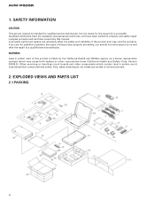
WARNING Lead in solder used in solder, avoid unprotected skin contact with the solder. EXPLODED VIEWS AND PARTS LIST 2.1 PACKING 31 2 SAFETY INFORMATION CAUTION This service manual is not meant for qualified service technicians; Qualified technicians have the necessary test equipment and tools, and have been trained to properly and safely repair complex products such as those covered by...
WARNING Lead in solder used in solder, avoid unprotected skin contact with the solder. EXPLODED VIEWS AND PARTS LIST 2.1 PACKING 31 2 SAFETY INFORMATION CAUTION This service manual is not meant for qualified service technicians; Qualified technicians have the necessary test equipment and tools, and have been trained to properly and safely repair complex products such as those covered by...
Service Manual
Page 3
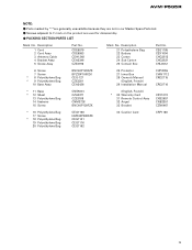
... Card 31 Remote Control Assy 32 Angel 33 Bracket CRY1070 CXB2657 CNB2351 CZN6467 * 16 Polyethylene Bag 17 Screw * 18 Polyethylene Bag 19 Polyethylene Bag 20 Polyethylene Bag CEG1158 HMF40P080FZK CEG1101 CEG1116 CEG1162 34 Caution Card CRP1188 3 Parts marked by "*"are generally unavailable because they are used for disassembly. - Description 1 Cord 2 Cord Assy 3 Antenna Cable 4 Bracket Assy 5 Screw Assy Part No.
... Card 31 Remote Control Assy 32 Angel 33 Bracket CRY1070 CXB2657 CNB2351 CZN6467 * 16 Polyethylene Bag 17 Screw * 18 Polyethylene Bag 19 Polyethylene Bag 20 Polyethylene Bag CEG1158 HMF40P080FZK CEG1101 CEG1116 CEG1162 34 Caution Card CRP1188 3 Parts marked by "*"are generally unavailable because they are used for disassembly. - Description 1 Cord 2 Cord Assy 3 Antenna Cable 4 Bracket Assy 5 Screw Assy Part No.
Service Manual
Page 6
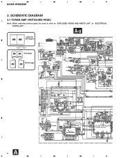
SCHEMATIC DIAGRAM 3.1 TUNER AMP UNIT(GUIDE PAGE) A Note: When ordering service parts, be sure to refer to "EXPLODED VIEWS AND PARTS LIST" or "ELECTRICAL PARTS LIST". 1 2 3 4 AVM-P505R 3. A-a Large size A-a A-b SCH diagram AUDIO SIGNAL COMPOSITE VIDEO SIGNAL Y SIGNAL COLOR SIGNAL RED SIGNAL SIYNCRONIZING SIGNAL A-a A-b Guide page B Detailed page A-a A-b C TUNU 2TUNU D A 6 1 2 3 4
SCHEMATIC DIAGRAM 3.1 TUNER AMP UNIT(GUIDE PAGE) A Note: When ordering service parts, be sure to refer to "EXPLODED VIEWS AND PARTS LIST" or "ELECTRICAL PARTS LIST". 1 2 3 4 AVM-P505R 3. A-a Large size A-a A-b SCH diagram AUDIO SIGNAL COMPOSITE VIDEO SIGNAL Y SIGNAL COLOR SIGNAL RED SIGNAL SIYNCRONIZING SIGNAL A-a A-b Guide page B Detailed page A-a A-b C TUNU 2TUNU D A 6 1 2 3 4

Service Manual
Page 14
1 2 3 4 AVM-P505R 4. PCB CONNECTION DIAGRAM 4.1 TUNER AMP UNIT A A TUNER AMP UNIT B TO MONITOR RESET ANT B C D A 14 1 2 VIDEO IN VIDEO OUT NAVI 3 IP-BUS O CORD ASSY 4
1 2 3 4 AVM-P505R 4. PCB CONNECTION DIAGRAM 4.1 TUNER AMP UNIT A A TUNER AMP UNIT B TO MONITOR RESET ANT B C D A 14 1 2 VIDEO IN VIDEO OUT NAVI 3 IP-BUS O CORD ASSY 4
Service Manual
Page 15
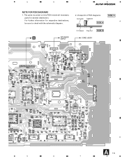
Viewpoint of PCB diagrams SIDE A Connector Capacitor A SIDE A P.C.Board Chip Part SIDE B CORD ASSY B C P-BUS OUT SUBWOOFER OUT L R REAR OUT L R FRONT OUT L R 5 6 7 D A 15 8 For further information for several destination. The parts mounted on this PCB include all necessary parts for respective destinations, be sure to check with the schematic diagram. B SPEAKER INPUT 2. 5 6 7 8 AVM-P505R NOTE FOR PCB DIAGRAMS 1.
Viewpoint of PCB diagrams SIDE A Connector Capacitor A SIDE A P.C.Board Chip Part SIDE B CORD ASSY B C P-BUS OUT SUBWOOFER OUT L R REAR OUT L R FRONT OUT L R 5 6 7 D A 15 8 For further information for several destination. The parts mounted on this PCB include all necessary parts for respective destinations, be sure to check with the schematic diagram. B SPEAKER INPUT 2. 5 6 7 8 AVM-P505R NOTE FOR PCB DIAGRAMS 1.
Service Manual
Page 20
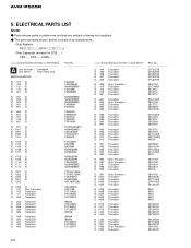
...: - Chip Resistor RS1/_S___J,RS1/__S___J Chip Capacitor (except for CQS.....) CKS....., CCS....., CSZS..... =====Circuit Symbol and No.===Part Name A Unit Number : CWM5804 Unit Name : Tuner Amp Unit MISCELLANEOUS IC 101 IC IC 102 IC IC 131 IC IC 171 IC IC 201 IC IC 251 IC IC 252 IC IC... 2SA1037K DTC114EK DTA114EK 2SC2412K IMX1 IMX1 IMX1 IMX1 IMX1 2SC2412K 2SC2412K 2SC2412K 2SC2412K 2SC2412K 2SC2412K DTC124EK 2SA1037K 2SA1162 2SC2412K 20 The part numbers shown below indicate chip components. Parts whose parts numbers are omitted are subject to being not supplied. - AVM-P505R 5.
...: - Chip Resistor RS1/_S___J,RS1/__S___J Chip Capacitor (except for CQS.....) CKS....., CCS....., CSZS..... =====Circuit Symbol and No.===Part Name A Unit Number : CWM5804 Unit Name : Tuner Amp Unit MISCELLANEOUS IC 101 IC IC 102 IC IC 131 IC IC 171 IC IC 201 IC IC 251 IC IC 252 IC IC... 2SA1037K DTC114EK DTA114EK 2SC2412K IMX1 IMX1 IMX1 IMX1 IMX1 2SC2412K 2SC2412K 2SC2412K 2SC2412K 2SC2412K 2SC2412K DTC124EK 2SA1037K 2SA1162 2SC2412K 20 The part numbers shown below indicate chip components. Parts whose parts numbers are omitted are subject to being not supplied. - AVM-P505R 5.

Service Manual
Page 30
... 5dB (STEREO MODE) VIDEO ADJUSTMENT Adjustment Method OSD Color Pattern Generator Adjustment Point TC1101 Adjustment Method (Switch Position) Monitor : a=Minimum LCD Panel Source Screen Bright Level White 100% , or 75% VR1301 Non Color Burst Signal Oscilloscope(2) : (S1 : ON) a 700mV ± 35mV (White : 100%) 530mV ± 35mV (White : 75%) Clock Sub-carrier for ten minutes to allow the circuits to further adjustments after switching power ON, let the tuner run for Encoder White 100% Non Color Burst Signal VR1302...
... 5dB (STEREO MODE) VIDEO ADJUSTMENT Adjustment Method OSD Color Pattern Generator Adjustment Point TC1101 Adjustment Method (Switch Position) Monitor : a=Minimum LCD Panel Source Screen Bright Level White 100% , or 75% VR1301 Non Color Burst Signal Oscilloscope(2) : (S1 : ON) a 700mV ± 35mV (White : 100%) 530mV ± 35mV (White : 75%) Clock Sub-carrier for ten minutes to allow the circuits to further adjustments after switching power ON, let the tuner run for Encoder White 100% Non Color Burst Signal VR1302...

Service Manual
Page 32
... select output Clock output for electronic volume Strobe pulse output for electronic volume Data output for electronic volume Tuner mute output Not used SD input FM stereo input GND Power supply Not used Visual source select 0 output Visual source select 1 output Rear monitor select output Guidance sound control output Not used Clock adjustment output Not used Chip select output for OSD IC Serial clock output for OSD IC Test program serial input Data output for OSD IC Not used Test terminal Signal level input from tuner Not used Memory hold output 32 AVM-P505R - Pin Functions (PD4923A) Pin...
... select output Clock output for electronic volume Strobe pulse output for electronic volume Data output for electronic volume Tuner mute output Not used SD input FM stereo input GND Power supply Not used Visual source select 0 output Visual source select 1 output Rear monitor select output Guidance sound control output Not used Clock adjustment output Not used Chip select output for OSD IC Serial clock output for OSD IC Test program serial input Data output for OSD IC Not used Test terminal Signal level input from tuner Not used Memory hold output 32 AVM-P505R - Pin Functions (PD4923A) Pin...

Service Manual
Page 33
... ground I IP BUS data input O IP BUS data output GND I PLL lock sense input I RDS demodulation clock input I 57kHz BP-OUT sense input I ID-LOGIC ready input I ACC power sense input I Back up power sense input I PLL IC data input I 24 VSS 25-55 NC 56 VDD 57-64 NC *PD6293A 17 32 33 16 Function and Operation Not used Not used Not used Remote control data input Display data input Not used Key data output Not used Crystal oscillator connection pin Crystal oscillator connection pin GND...
... ground I IP BUS data input O IP BUS data output GND I PLL lock sense input I RDS demodulation clock input I 57kHz BP-OUT sense input I ID-LOGIC ready input I ACC power sense input I Back up power sense input I PLL IC data input I 24 VSS 25-55 NC 56 VDD 57-64 NC *PD6293A 17 32 33 16 Function and Operation Not used Not used Not used Remote control data input Display data input Not used Key data output Not used Crystal oscillator connection pin Crystal oscillator connection pin GND...

Service Manual
Page 34
...-64 ADD8-12 O Format C C C Function and Operation Open ROM output control ROM enable ROM address Analog power supply 5V power supply Connect to GND Select input RDS demodulation clock input RDS demodulation data input Open RDS LK signal input Reset input Connect to GND Connect to GND Crystal oscillating element connection pin Crystal oscillating element connection pin GND Reset output Open Communication ready output ROM address ROM address ROM data input GND Test terminal Communication clock input Communication data output Communication data input Open 5V SD signal input Open ROM address...
...-64 ADD8-12 O Format C C C Function and Operation Open ROM output control ROM enable ROM address Analog power supply 5V power supply Connect to GND Select input RDS demodulation clock input RDS demodulation data input Open RDS LK signal input Reset input Connect to GND Connect to GND Crystal oscillating element connection pin Crystal oscillating element connection pin GND Reset output Open Communication ready output ROM address ROM address ROM data input GND Test terminal Communication clock input Communication data output Communication data input Open 5V SD signal input Open ROM address...
Service Manual
Page 38
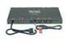
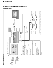
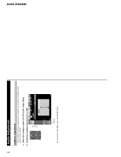
... the parking brake switch's + side lead wire. This product Monitor [AVX-505] or [AVD-505] Yellow/black Connect to a muting line of any connections. Please be sure to connect to connect Insert the parking break switch's + side lead wire. Fuse resistor Yellow To lighting switch terminal. IP-Bus cable IP-Bus input (Blue) Green RGB input To a Pioneer unit that the vehicle is stopped. AVM-P505R 8. OPERATIONS AND SPECIFICATIONS 8.1 OPERATIONS 38 Basic System Connection + side Earth side Blue/yellow Used to speakers.
... the parking brake switch's + side lead wire. This product Monitor [AVX-505] or [AVD-505] Yellow/black Connect to a muting line of any connections. Please be sure to connect to connect Insert the parking break switch's + side lead wire. Fuse resistor Yellow To lighting switch terminal. IP-Bus cable IP-Bus input (Blue) Green RGB input To a Pioneer unit that the vehicle is stopped. AVM-P505R 8. OPERATIONS AND SPECIFICATIONS 8.1 OPERATIONS 38 Basic System Connection + side Earth side Blue/yellow Used to speakers.
Service Manual
Page 40
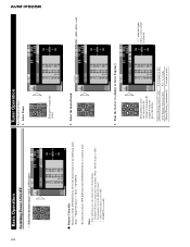
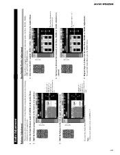
.... 3. Remote Controller Each press of the SOURCE button selects the desired source in the following cases, the sound source will not change: * No Multi-CD player is connected to this product. (When "M-CD" display is OFF.) * No magazine is set in the Multi-CD player. * AUX (external input) is set to a higher or lower frequency. Manual Tuning (step by changing the length of Tuner 1. Tune the receiver to OFF. Tuner Operation Basic Operation of time...
.... 3. Remote Controller Each press of the SOURCE button selects the desired source in the following cases, the sound source will not change: * No Multi-CD player is connected to this product. (When "M-CD" display is OFF.) * No magazine is set in the Multi-CD player. * AUX (external input) is set to a higher or lower frequency. Manual Tuning (step by changing the length of Tuner 1. Tune the receiver to OFF. Tuner Operation Basic Operation of time...
Service Manual
Page 41
... Function Menu is being received. ** During AM reception, you can be possible if the frequency is changed only when the multi-station is automatically canceled. AVM-P505R 41 Raise or lower the volume. Turn the source OFF. Tuner Operation 4. Entering the Function Menu In this menu you can select tuner functions. • In modes other than LOCAL, you cannot switch to the TA mode. can use these functions. • Select the desired mode...
... Function Menu is being received. ** During AM reception, you can be possible if the frequency is changed only when the multi-station is automatically canceled. AVM-P505R 41 Raise or lower the volume. Turn the source OFF. Tuner Operation 4. Entering the Function Menu In this menu you can select tuner functions. • In modes other than LOCAL, you cannot switch to the TA mode. can use these functions. • Select the desired mode...
Service Manual
Page 42
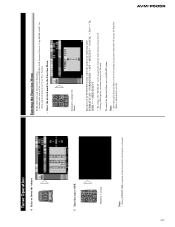
... the connected multi CD player type. AVM-P505R 42 Using Multi-CD Players This product can control one or more multi-CD players. Basic Operation of a disc or reading disc information, when the power is turned ON or a new disc is displayed. • If the multi-CD player cannot operate properly, an error message such as verifying the presence of Multi-CD Players 1. Select the multi-CD player source. Disc number (Button Number) Each press changes the Source...
... the connected multi CD player type. AVM-P505R 42 Using Multi-CD Players This product can control one or more multi-CD players. Basic Operation of a disc or reading disc information, when the power is turned ON or a new disc is displayed. • If the multi-CD player cannot operate properly, an error message such as verifying the presence of Multi-CD Players 1. Select the multi-CD player source. Disc number (Button Number) Each press changes the Source...
Service Manual
Page 43
... lower the volume. If you start playing a disc on a 50-Disc type multi-CD player before reading of functions. When two or more multi-CD players are installed, their priorities must be specified. Just press the number corresponding to the disc you from using a number of information on all the discs in . Press button 3.) AVM-P505R 43 Hold for 6-Disc, 12-Disc types) You can select discs directly with...
... lower the volume. If you start playing a disc on a 50-Disc type multi-CD player before reading of functions. When two or more multi-CD players are installed, their priorities must be specified. Just press the number corresponding to the disc you from using a number of information on all the discs in . Press button 3.) AVM-P505R 43 Hold for 6-Disc, 12-Disc types) You can select discs directly with...
Service Manual
Page 44
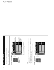
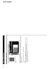
... changes the Mode... Initially, sub-woofer output is ON. • After entering the Audio Menu, if you want to adjust in Audio Menu. Each press of the AUDIO button selects the mode in the SUBWOOFER1. AVM-P505R 44 Audio Adjustment Entering the Audio Menu • Select the mode you do not perform an operation which 30 seconds, the Audio Menu is automatically canceled. Note: • You can select the "SUBWOOFER2" mode only when sub...
... changes the Mode... Initially, sub-woofer output is ON. • After entering the Audio Menu, if you want to adjust in Audio Menu. Each press of the AUDIO button selects the mode in the SUBWOOFER1. AVM-P505R 44 Audio Adjustment Entering the Audio Menu • Select the mode you do not perform an operation which 30 seconds, the Audio Menu is automatically canceled. Note: • You can select the "SUBWOOFER2" mode only when sub...
Service Manual
Page 45
.... AVM-P505R 45 Select bass (BASS) / middle (MID) / treble (TREBLE) in the Audio Menu. 1. The display shows "+6" - To cancel the Audio Menu, press the BAND button. Select the Fader/Balance mode (FADER) in the Audio Menu. 2. "REAR +15" is displayed as it moves from left or right speaker, respectively. Note: • When using 2-speaker system, set FADER to The tone for the other Bass, Middle or Treble Adjustment. To cancel the Audio Menu...
.... AVM-P505R 45 Select bass (BASS) / middle (MID) / treble (TREBLE) in the Audio Menu. 1. The display shows "+6" - To cancel the Audio Menu, press the BAND button. Select the Fader/Balance mode (FADER) in the Audio Menu. 2. "REAR +15" is displayed as it moves from left or right speaker, respectively. Note: • When using 2-speaker system, set FADER to The tone for the other Bass, Middle or Treble Adjustment. To cancel the Audio Menu...
Service Manual
Page 46
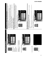
"LOUD" To cancel the Audio Menu, press the BAND button. AVM-P505R 46 Audio Adjustment Loudness Adjustment The Loudness function compensates for deficiencies in the Audio Menu. 2. Switch the Loudness function ON or OFF. Select the Loudness mode (LOUD) in the low and high sound ranges at low volume. 1.
"LOUD" To cancel the Audio Menu, press the BAND button. AVM-P505R 46 Audio Adjustment Loudness Adjustment The Loudness function compensates for deficiencies in the Audio Menu. 2. Switch the Loudness function ON or OFF. Select the Loudness mode (LOUD) in the low and high sound ranges at low volume. 1.
Service Manual
Page 47
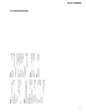
... undesired signal level: 100 dBf) AM tuner Frequency range 530 - 1,710 kHz (10kHz) Usable sensitivity 18 mV (S/N: 20 dB) Selectivity 50 dB (±10 kHz) Video Composit input level 1V/75 ½ (±0.2 V) Composit output level 1V/75 ½ (±0.2 V) 8.2 SPECIFICATIONS AVM-P505R Maximum power output 40 W ´ 4 Load impedance 4 W (4 - 8 W allowable) Preout output level/output impedance 500 mV/1 k½ Sub-woofer output Crossover frequency...
... undesired signal level: 100 dBf) AM tuner Frequency range 530 - 1,710 kHz (10kHz) Usable sensitivity 18 mV (S/N: 20 dB) Selectivity 50 dB (±10 kHz) Video Composit input level 1V/75 ½ (±0.2 V) Composit output level 1V/75 ½ (±0.2 V) 8.2 SPECIFICATIONS AVM-P505R Maximum power output 40 W ´ 4 Load impedance 4 W (4 - 8 W allowable) Preout output level/output impedance 500 mV/1 k½ Sub-woofer output Crossover frequency...

