
Service Manual
Page 2
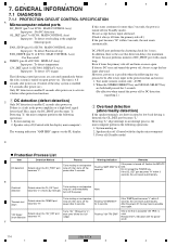
... (input/output terminals, screwheads, metal overlays, control shaft, etc.). 1 2 3 4 SAFTY INFORMATION A This service manual is not meant for qualified service technicians; If you should not be obtained at a nominal charge from visual inspection nor the protection afforded by marking with plug reversed (Using AC adapter plug as the PIONEER recommended replacement one, shown in the parts list in this Service Manual, may be above 0.5 mA Test all...
... (input/output terminals, screwheads, metal overlays, control shaft, etc.). 1 2 3 4 SAFTY INFORMATION A This service manual is not meant for qualified service technicians; If you should not be obtained at a nominal charge from visual inspection nor the protection afforded by marking with plug reversed (Using AC adapter plug as the PIONEER recommended replacement one, shown in the parts list in this Service Manual, may be above 0.5 mA Test all...
Service Manual
Page 3
... adjustments or specification confirmation is indispensable. BLOCK DIAGRAM AND SCHEMATIC DIAGRAM 18 3.1 BLOCK DIAGRAM...18 3.1.1 AUDIO SECTION ...18 3.1.2 VIDEO and DISPLAY SECTIONS ...20 3.1.3 DSP SECTION ...22 3.1.4 POWER SUPPLY SECTION ...24 3.2 OVERALL WIRING DIAGRAM ...26 3.3 MULTI CH I/O and AUDIO CONNECT ASSYS 28 3.4 COMPOSITE V ASSY ...30 3.5 S VIDEO ASSY...32 3.6 COMPONENT ASSY...34 3.7 OPTICAL-IN,H.P,FRONT-IN,FRONT-IN CONNECT and 12VTRIG ASSYS 36 3.8 MAIN CONTROL ASSY (1/3) ...38 3.9 MAIN CONTROL ASSY (2/3) ...40 3.10 MAIN CONTROL...
... adjustments or specification confirmation is indispensable. BLOCK DIAGRAM AND SCHEMATIC DIAGRAM 18 3.1 BLOCK DIAGRAM...18 3.1.1 AUDIO SECTION ...18 3.1.2 VIDEO and DISPLAY SECTIONS ...20 3.1.3 DSP SECTION ...22 3.1.4 POWER SUPPLY SECTION ...24 3.2 OVERALL WIRING DIAGRAM ...26 3.3 MULTI CH I/O and AUDIO CONNECT ASSYS 28 3.4 COMPOSITE V ASSY ...30 3.5 S VIDEO ASSY...32 3.6 COMPONENT ASSY...34 3.7 OPTICAL-IN,H.P,FRONT-IN,FRONT-IN CONNECT and 12VTRIG ASSYS 36 3.8 MAIN CONTROL ASSY (1/3) ...38 3.9 MAIN CONTROL ASSY (2/3) ...40 3.10 MAIN CONTROL...

Service Manual
Page 4
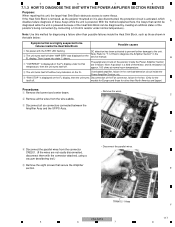
... THE POWER AMPLIFIER SECTION REMOVED 117 7.1.4 DISASSEMBLY...120 7.1.5 TROUBLE SHOOTING OF THE DSP ASSY 124 7.2 PARTS...133 7.2.1 IC ...133 7.3 CLEANING...142 8. PCB CONNECTION DIAGRAM ...62 4.1 MULTI CH I/O ASSY ...63 4.2 AUDIO CONNECT ASSY ...64 A 4.3 COMPOSITE V ASSY...65 4.4 S VIDEO ASSY ...66 4.5 VIDEO SIDE and OPTICAL-IN ASSYS 67 4.6 COMPONENT ASSY ...68 4.7 FRONT IN and FRONT-IN CONNECT ASSYS 69 4.8 MAIN CONTROL ASSY ...70 4.9 DISPLAY ASSY...74 4.10 HEADPHONE, VOLUME and MULTI...
... THE POWER AMPLIFIER SECTION REMOVED 117 7.1.4 DISASSEMBLY...120 7.1.5 TROUBLE SHOOTING OF THE DSP ASSY 124 7.2 PARTS...133 7.2.1 IC ...133 7.3 CLEANING...142 8. PCB CONNECTION DIAGRAM ...62 4.1 MULTI CH I/O ASSY ...63 4.2 AUDIO CONNECT ASSY ...64 A 4.3 COMPOSITE V ASSY...65 4.4 S VIDEO ASSY ...66 4.5 VIDEO SIDE and OPTICAL-IN ASSYS 67 4.6 COMPONENT ASSY ...68 4.7 FRONT IN and FRONT-IN CONNECT ASSYS 69 4.8 MAIN CONTROL ASSY ...70 4.9 DISPLAY ASSY...74 4.10 HEADPHONE, VOLUME and MULTI...
Service Manual
Page 5
... Parts Microphone (for Amplifiers ** Measured by Audio Spectrum Analyzer Composite Video / S-Video Section Input (Sensitivity/Impedance 1 Vp-p/75Ω Output (Level/Impedance 1 Vp-p/75Ω Signal-to-Noise Ratio 65 dB Frequency Response 5 Hz to 10 MHz dB Component Video Sectio Input (Sensitivity/Impedance 1 Vp-p/75Ω Output (Level/Impedance 1 Vp-p/75Ω Signal-to-Noise Ratio 65 dB Frequency Response 5 Hz to 40 MHz dB FM Tuner Sectio Frequency...
... Parts Microphone (for Amplifiers ** Measured by Audio Spectrum Analyzer Composite Video / S-Video Section Input (Sensitivity/Impedance 1 Vp-p/75Ω Output (Level/Impedance 1 Vp-p/75Ω Signal-to-Noise Ratio 65 dB Frequency Response 5 Hz to 10 MHz dB Component Video Sectio Input (Sensitivity/Impedance 1 Vp-p/75Ω Output (Level/Impedance 1 Vp-p/75Ω Signal-to-Noise Ratio 65 dB Frequency Response 5 Hz to 40 MHz dB FM Tuner Sectio Frequency...
Service Manual
Page 6
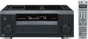
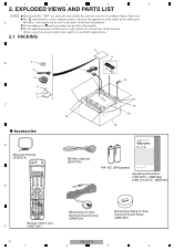
... STEREO ACOUSTIC SIGNAL MIDNIGHT/ AUTO SURR EQ SELECT LOUDNESS SHIFT EFFECT /CH SEL SLEEP DIALOG E RECEIVER Remote Control Unit ( AXD7381 ) 8 9 1 10 12 14 15 13 16 AUDIO/VIDEO MULTI-CHANNEL RECEIVER VSX-52TX FM Wire Antenna (ADH7030) "AA" IEC LR6 batteries Operating Instructions Operating Instructions (VSX-52TX : ARB7302) (VSX-1014TX-K : ARB7305) Microphone for Auto Surround Sound Setup (APM7004) Microphone Stand for disassembly. For the applying amount of lubricants or glue, follow the instructions in our Master Spare Parts...
... STEREO ACOUSTIC SIGNAL MIDNIGHT/ AUTO SURR EQ SELECT LOUDNESS SHIFT EFFECT /CH SEL SLEEP DIALOG E RECEIVER Remote Control Unit ( AXD7381 ) 8 9 1 10 12 14 15 13 16 AUDIO/VIDEO MULTI-CHANNEL RECEIVER VSX-52TX FM Wire Antenna (ADH7030) "AA" IEC LR6 batteries Operating Instructions Operating Instructions (VSX-52TX : ARB7302) (VSX-1014TX-K : ARB7305) Microphone for Auto Surround Sound Setup (APM7004) Microphone Stand for disassembly. For the applying amount of lubricants or glue, follow the instructions in our Master Spare Parts...

Service Manual
Page 18
BLOCK DIAGRAM AND SCHEMATIC DIAGRAM 3.1 BLOCK DIAGRAM 3.1.1 AUDIO SECTION A G OPTICAL-IN ASSY B I FRONT-IN ASSY AC REAR TOP ASSY C J FRONT-IN CONNECT ASSY D A MULTI CH I/O ASSY E F 18 1 B AUDIO CONNECT ASSY VSX-52TX 2 3 4 1 2 3 4 3.
BLOCK DIAGRAM AND SCHEMATIC DIAGRAM 3.1 BLOCK DIAGRAM 3.1.1 AUDIO SECTION A G OPTICAL-IN ASSY B I FRONT-IN ASSY AC REAR TOP ASSY C J FRONT-IN CONNECT ASSY D A MULTI CH I/O ASSY E F 18 1 B AUDIO CONNECT ASSY VSX-52TX 2 3 4 1 2 3 4 3.
Service Manual
Page 114
... detects DC once and turned the power off , flashes the MCACC Flashing "AMP ERR" for 3 LED. System muting on once again. Speaker relay off (Control with a main loop. Even if turns the primary side off . When the STEREO/DIRECT key and SIGNAL SELECT key are both held pressed for maximum 20 msec because performs monitor of IC3001: DISPLAY Assy) Input port : To detect 12V trigger...
... detects DC once and turned the power off , flashes the MCACC Flashing "AMP ERR" for 3 LED. System muting on once again. Speaker relay off (Control with a main loop. Even if turns the primary side off . When the STEREO/DIRECT key and SIGNAL SELECT key are both held pressed for maximum 20 msec because performs monitor of IC3001: DISPLAY Assy) Input port : To detect 12V trigger...
Service Manual
Page 117
... unit turns itself off after "AMP ERR" was displayed on the FL display, then the unit turns Disconnection of the Fan connector, failure in the service manual. models for Europe and those shown in the table below: Symptoms that are highly suspected to be failures inside the Power Amplifier Section are not easily disconnected, disconnect them with the STBY LED flashing DC...
... unit turns itself off after "AMP ERR" was displayed on the FL display, then the unit turns Disconnection of the Fan connector, failure in the service manual. models for Europe and those shown in the table below: Symptoms that are highly suspected to be failures inside the Power Amplifier Section are not easily disconnected, disconnect them with the STBY LED flashing DC...

Service Manual
Page 124
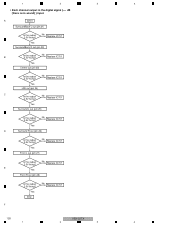
... No outputting it ? 1 2 3 4 7.1.5 TROUBLE SHOOTING OF THE DSP ASSY • When a sound is not out in the multi-channel signal playback or surround mode with the digital signal input. (SurroundBack is not out with the setting.) • Suppose CR to B connector CN901 Is connector inserted tight ? A • This shows failure analysis of the DSP module floats from the chassis. And this unit may not work...
... No outputting it ? 1 2 3 4 7.1.5 TROUBLE SHOOTING OF THE DSP ASSY • When a sound is not out in the multi-channel signal playback or surround mode with the digital signal input. (SurroundBack is not out with the setting.) • Suppose CR to B connector CN901 Is connector inserted tight ? A • This shows failure analysis of the DSP module floats from the chassis. And this unit may not work...

Service Manual
Page 126
... ? No Check the other Assy (the periphery of each channel in the digital signal (there is oscillated only at analog input. No Replace IC801 Does oscillation stop? B Yes MCKO1 (pin 23) Step 8: DSP output (digital) • Digital output of microcomputer) Yes Center/LFE data (pin 5) C Yes XTO (pin 29) X601 is a sound) input. PDN (pin 31) Yes SurroundBack L/R data (pin 4) Is pin...
... ? No Check the other Assy (the periphery of each channel in the digital signal (there is oscillated only at analog input. No Replace IC801 Does oscillation stop? B Yes MCKO1 (pin 23) Step 8: DSP output (digital) • Digital output of microcomputer) Yes Center/LFE data (pin 5) C Yes XTO (pin 29) X601 is a sound) input. PDN (pin 31) Yes SurroundBack L/R data (pin 4) Is pin...

Service Manual
Page 127
...) Is pin 28 outputting it ? 5 6 • Each channel output in the digital signal (there is no sound) ) input. Yes No Replace IC801 Front L/R data (pin 7) Is the output 0V fixing? No Replace IC701 Yes Surround L out (pin 25) Is pin 25 outputting it ? Yes End No Replace IC701 F VSX-52TX 127 5 6 7 8 No Replace IC801 Yes Surround L/R data (pin 6) Is the output 0V fixing? No Replace IC701 Yes Surround R out (pin...
...) Is pin 28 outputting it ? 5 6 • Each channel output in the digital signal (there is no sound) ) input. Yes No Replace IC801 Front L/R data (pin 7) Is the output 0V fixing? No Replace IC701 Yes Surround L out (pin 25) Is pin 25 outputting it ? Yes End No Replace IC701 F VSX-52TX 127 5 6 7 8 No Replace IC801 Yes Surround L/R data (pin 6) Is the output 0V fixing? No Replace IC701 Yes Surround R out (pin...
Service Manual
Page 128
...) C Is the output 2.5V fixing? No Replace IC701 Yes Surround L out (pin 25) Is the output 2.5V fixing? No Replace IC701 E Yes Front R out (pin 28) Is the output 2.5V fixing? A IC701 SurroundBack L out (pin 21) Is the output 2.5V fixing? Yes End No Replace IC701 F 128 VSX-52TX 1 2 3 4 1 2 3 4 • Each channel output in the digital signal (-∞ dB (there is no sound) ) input. No Replace IC701 Yes Front...
...) C Is the output 2.5V fixing? No Replace IC701 Yes Surround L out (pin 25) Is the output 2.5V fixing? No Replace IC701 E Yes Front R out (pin 28) Is the output 2.5V fixing? A IC701 SurroundBack L out (pin 21) Is the output 2.5V fixing? Yes End No Replace IC701 F 128 VSX-52TX 1 2 3 4 1 2 3 4 • Each channel output in the digital signal (-∞ dB (there is no sound) ) input. No Replace IC701 Yes Front...

Service Manual
Page 133
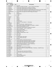
... GND − Interface power supply (3.3V) O Digital audio data (Surround Back L/R) O Digital audio data (Center/Subwoofer) O Digital audio data (Surround L/R) O Digital audio data (Front L/R) − Core power supply (1.25V) O General-purpose port − General-purpose port: LOCK O General-purpose port − Core GND O General-purpose port O General-purpose port O General-purpose port O General-purpose port − Interface power supply (3.3V) O General-purpose port O General-purpose port − GND for S/PDIF O General-purpose port I Test pin O General-purpose...
... GND − Interface power supply (3.3V) O Digital audio data (Surround Back L/R) O Digital audio data (Center/Subwoofer) O Digital audio data (Surround L/R) O Digital audio data (Front L/R) − Core power supply (1.25V) O General-purpose port − General-purpose port: LOCK O General-purpose port − Core GND O General-purpose port O General-purpose port O General-purpose port O General-purpose port − Interface power supply (3.3V) O General-purpose port O General-purpose port − GND for S/PDIF O General-purpose port I Test pin O General-purpose...
Service Manual
Page 137
NC O DIR reset signal I Lock/Unlock signal from the display microcomputer) (pulldown) H I INT for 1394 (Not used L O Error detection signal of DSP microcomputer L O Mode selection of 1st DSP O Communication enabling signal to the display microcomputer H O OSD-IC reset signal L: reset, H: release reset C O OSD-IC chip select signal H O At data transfer to the OSD-IC: "H" O Reset for 1394 "L" fixed. Pin Name 1 12VTRIGGER 2 DISP RST 3 DISP EN 4 DISP RDY 5 OSD/DISP DI 6 DISP DO...
NC O DIR reset signal I Lock/Unlock signal from the display microcomputer) (pulldown) H I INT for 1394 (Not used L O Error detection signal of DSP microcomputer L O Mode selection of 1st DSP O Communication enabling signal to the display microcomputer H O OSD-IC reset signal L: reset, H: release reset C O OSD-IC chip select signal H O At data transfer to the OSD-IC: "H" O Reset for 1394 "L" fixed. Pin Name 1 12VTRIGGER 2 DISP RST 3 DISP EN 4 DISP RDY 5 OSD/DISP DI 6 DISP DO...
Service Manual
Page 143
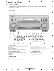
... TUNER VIDEO2 MASTER VOLUME C 10 11 12 13 14 15 16 17 18 19 TUNER CONTROL TUNER EDIT TUNING/ STATION MULTI JOG BAND MPX MIDNIGHT/ LOUDNESS SYSTEM SETUP RETURN MULTI ROOM CONTROL ON/OFF TONE ACOUSTIC DIALOG MULTI CH EQ ENHANCEMENT IN MULTI JOG SIGNAL SELECT EXTENDED MODE SPEAKERS MCACC SETUP MIC VIDEO2 INPUT MULTI JOG MULTI JOG PHONES D DIGITAL IN S-VIDEO VIDEO L AUDIO R 24 23 22 1 MULTI JOG dial Use the MULTI JOG dial to select various settings and menu options. 2 STANDBY/ON Switches the receiver...
... TUNER VIDEO2 MASTER VOLUME C 10 11 12 13 14 15 16 17 18 19 TUNER CONTROL TUNER EDIT TUNING/ STATION MULTI JOG BAND MPX MIDNIGHT/ LOUDNESS SYSTEM SETUP RETURN MULTI ROOM CONTROL ON/OFF TONE ACOUSTIC DIALOG MULTI CH EQ ENHANCEMENT IN MULTI JOG SIGNAL SELECT EXTENDED MODE SPEAKERS MCACC SETUP MIC VIDEO2 INPUT MULTI JOG MULTI JOG PHONES D DIGITAL IN S-VIDEO VIDEO L AUDIO R 24 23 22 1 MULTI JOG dial Use the MULTI JOG dial to select various settings and menu options. 2 STANDBY/ON Switches the receiver...
Service Manual
Page 144
... select the component connected to the MULTI CH IN terminals (for recall. 24 PHONES jack Use to select station presets and radio frequencies. Use Loudness to confirm and exit the current menu screen. MPX C Press to receive a radio broadcast in mono. 12 MIDNIGHT/LOUDNESS Use Midnight when listening to control the sub room from the speakers. AUDIO/VIDEO MULTI-CHANNEL RECEIVER DVD/LD VSX-52TX TV/SAT CD DVR/VCR TACPDE-R/M/ D VIDEO1 TUNER MASTER VOLUME VIDEO2 23 System Setup menu controls SYSTEM SETUP Use...
... select the component connected to the MULTI CH IN terminals (for recall. 24 PHONES jack Use to select station presets and radio frequencies. Use Loudness to confirm and exit the current menu screen. MPX C Press to receive a radio broadcast in mono. 12 MIDNIGHT/LOUDNESS Use Midnight when listening to control the sub room from the speakers. AUDIO/VIDEO MULTI-CHANNEL RECEIVER DVD/LD VSX-52TX TV/SAT CD DVR/VCR TACPDE-R/M/ D VIDEO1 TUNER MASTER VOLUME VIDEO2 23 System Setup menu controls SYSTEM SETUP Use...
Service Manual
Page 145
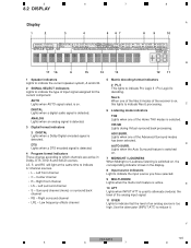
... the level of the Advanced Surround modes has been selected. E 10 ATT Lights when INPUT ATT is switched on, the corresponding indicator shows in Dolby, DTS, DVD-A and SACD sources. Use the attenuator (INPUT ATT) to indicate Pro Logic II / Pro Logic IIx decoding. Surround channel (mono) or surround back channel • RS - Neo:6 When one of the receiver is active. ADV.SURR. Low frequency effects channel 5 Matrix decoding format indicators...
... the level of the Advanced Surround modes has been selected. E 10 ATT Lights when INPUT ATT is switched on, the corresponding indicator shows in Dolby, DTS, DVD-A and SACD sources. Use the attenuator (INPUT ATT) to indicate Pro Logic II / Pro Logic IIx decoding. Surround channel (mono) or surround back channel • RS - Neo:6 When one of the receiver is active. ADV.SURR. Low frequency effects channel 5 Matrix decoding format indicators...
Service Manual
Page 147
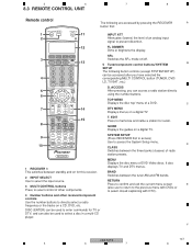
.... 5 6 7 8 8.3 REMOTE CONTROL UNIT Remote control The following button controls (except SYSTEM SETUP) can be used to directly select a radio frequency or the tracks on for this receiver. 2 INPUT SELECT Use to select the input source. 3 MULTI CONTROL buttons Press to select control of other receiver/component controls Use the number buttons to enter commands for recall. C DTV MENU Displays menus on a digital TV. 8 9 10 DTV ON/OFF REC DTV INFO MUTE TUNER DISPLAY REC STOP MPX AUDIO CH RETURN SUBTITLE HDD DVD CH CH RECEIVER CONTROL THX STANDARD ADV.SURR STEREO...
.... 5 6 7 8 8.3 REMOTE CONTROL UNIT Remote control The following button controls (except SYSTEM SETUP) can be used to directly select a radio frequency or the tracks on for this receiver. 2 INPUT SELECT Use to select the input source. 3 MULTI CONTROL buttons Press to select control of other receiver/component controls Use the number buttons to enter commands for recall. C DTV MENU Displays menus on a digital TV. 8 9 10 DTV ON/OFF REC DTV INFO MUTE TUNER DISPLAY REC STOP MPX AUDIO CH RETURN SUBTITLE HDD DVD CH CH RECEIVER CONTROL THX STANDARD ADV.SURR STEREO...
Service Manual
Page 148
... button. SURR Use to switch between the various surround modes 8 Component control buttons C The main buttons ( , , etc.) are dedicated to control the TV assigned to adjust the volume on /off . AUTO SURR (when connected to control a component after you 're playing and select multichannel or stereo playback as Dolby Pro Logic IIx Music and Neo:6 Music CH RETURN Returns to adjust the level. frequencies. mono will improve the sound quality. SUBTITLE Displays/changes the subtitles included in multilingual DVD-Video discs. buttons...
... button. SURR Use to switch between the various surround modes 8 Component control buttons C The main buttons ( , , etc.) are dedicated to control the TV assigned to adjust the volume on /off . AUTO SURR (when connected to control a component after you 're playing and select multichannel or stereo playback as Dolby Pro Logic IIx Music and Neo:6 Music CH RETURN Returns to adjust the level. frequencies. mono will improve the sound quality. SUBTITLE Displays/changes the subtitles included in multilingual DVD-Video discs. buttons...
Service Manual
Page 149
... setup mode, from which you 're setting the remote to control other components connected to change Dolby Pro Logic IIx and Neo:6 Music parameter settings. STANDBY/ON LISTESNEILNEGCMT ODE MULTI JOG ENTER 30 30 AUDIO/VIDEO MULTI-CHANNEL RECEIVER DVD/LD VSX-52TX TV/SAT CD DVR/VCR TACPDE-R/M/ D VIDEO1 TUNER VIDEO2 MASTER VOLUME 7m C D E F VSX-52TX 149 5 6 7 8 The following commands are obstacles between the remote control and the receiver's remote sensor. • Direct sunlight or fluorescent light...
... setup mode, from which you 're setting the remote to control other components connected to change Dolby Pro Logic IIx and Neo:6 Music parameter settings. STANDBY/ON LISTESNEILNEGCMT ODE MULTI JOG ENTER 30 30 AUDIO/VIDEO MULTI-CHANNEL RECEIVER DVD/LD VSX-52TX TV/SAT CD DVR/VCR TACPDE-R/M/ D VIDEO1 TUNER VIDEO2 MASTER VOLUME 7m C D E F VSX-52TX 149 5 6 7 8 The following commands are obstacles between the remote control and the receiver's remote sensor. • Direct sunlight or fluorescent light...


