

Leaflet
Page 1
..., Concert, Disco, Cyber) • Dynamic Bass Boost (Beat, Punch, Blast) • Incredible Surround™ • Interactive Dashboard display with VU meter • 3 way Bass Reflex Speaker System • Plays CD, CD-R and CD-RW discs • FM/AM Digital Tuning with 40 presets • Full Dual Tape Deck with Auto Replay...
..., Concert, Disco, Cyber) • Dynamic Bass Boost (Beat, Punch, Blast) • Incredible Surround™ • Interactive Dashboard display with VU meter • 3 way Bass Reflex Speaker System • Plays CD, CD-R and CD-RW discs • FM/AM Digital Tuning with 40 presets • Full Dual Tape Deck with Auto Replay...

Leaflet
Page 2
...shows volume level and musical amplitude during playback. 31-key Remote Control This infrared remote control operates volume +/-, all volume levels. 3-Way Bass Reflex Speaker System Equipped with one 6 1/2" woofer and one 2" tweeter and one or multiple discs, to another to create a modern and functional design. ... of a CD or a CD program. Demo Mode Functions always. Next/Previous Skip This two button feature offers you to interrupt demo mode. FWC555 Sound Enhancement 2 x 140 Watts RMS Stereo 140 watts continuous RMS power output per channel, at 6 Ohms, from your favorite CD or an...
...shows volume level and musical amplitude during playback. 31-key Remote Control This infrared remote control operates volume +/-, all volume levels. 3-Way Bass Reflex Speaker System Equipped with one 6 1/2" woofer and one 2" tweeter and one or multiple discs, to another to create a modern and functional design. ... of a CD or a CD program. Demo Mode Functions always. Next/Previous Skip This two button feature offers you to interrupt demo mode. FWC555 Sound Enhancement 2 x 140 Watts RMS Stereo 140 watts continuous RMS power output per channel, at 6 Ohms, from your favorite CD or an...

User manual
Page 3
... Remote Control 7 Front Panel 8-9 Rear Panel 10 First Time Setup First Time Setup 11 Where Do You Start 11 Battery Installation 11 Antenna Connections 11 Speaker Connections 12 Optional Connections 12 Plug & Play 13 Demo 13 Power Settings 14 Sound Options Volume Control, MAX Sound, Digital Sound Control (DSC 15 Virtual...
... Remote Control 7 Front Panel 8-9 Rear Panel 10 First Time Setup First Time Setup 11 Where Do You Start 11 Battery Installation 11 Antenna Connections 11 Speaker Connections 12 Optional Connections 12 Plug & Play 13 Demo 13 Power Settings 14 Sound Options Volume Control, MAX Sound, Digital Sound Control (DSC 15 Virtual...

User manual
Page 5
.... ting dust on this product meets the ENERGY STAR guidelines for about one . ers, or anti-static spray intended for remote control G Two speakers G AM loop antenna and FM wire antenna G Owner's manual, Quick Use Guide and product registra- G The lens may cloud over if you are ...experience G 2 x 140 watts RMS Stereo. If lens cloud- Leave the power on the lens. Acknowledgement Energy Star As an ENERGY STAR Partner, Philips has determined that this system. Helpful Hint • If you suddenly move the CD player from gathering on for energy effi- We hope you may...
.... ting dust on this product meets the ENERGY STAR guidelines for about one . ers, or anti-static spray intended for remote control G Two speakers G AM loop antenna and FM wire antenna G Owner's manual, Quick Use Guide and product registra- G The lens may cloud over if you are ...experience G 2 x 140 watts RMS Stereo. If lens cloud- Leave the power on the lens. Acknowledgement Energy Star As an ENERGY STAR Partner, Philips has determined that this system. Helpful Hint • If you suddenly move the CD player from gathering on for energy effi- We hope you may...
User manual
Page 10
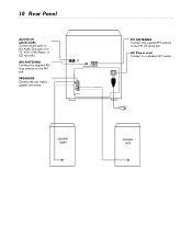
AC Power cord Connect to the AM jack. speaker (right) speaker (left) AM ANTENNA Connect the supplied AM loop antenna to a standard AC outlet. AUX/ CDR IN AM ANTENNA FM ANTENNA R+ L + SPEAKERS AC MAINS FM ANTENNA Connect the supplied FM antenna to the Audio Out jacks of a TV, VCR, DVD Player, or CD recorder. SPEAKERS Connect the red +/black speaker wires here. 10 Rear Panel AUDIO IN (AUX/CDR) Connect these jacks to the FM (75 ohm) jack .
AC Power cord Connect to the AM jack. speaker (right) speaker (left) AM ANTENNA Connect the supplied AM loop antenna to a standard AC outlet. AUX/ CDR IN AM ANTENNA FM ANTENNA R+ L + SPEAKERS AC MAINS FM ANTENNA Connect the supplied FM antenna to the Audio Out jacks of a TV, VCR, DVD Player, or CD recorder. SPEAKERS Connect the red +/black speaker wires here. 10 Rear Panel AUDIO IN (AUX/CDR) Connect these jacks to the FM (75 ohm) jack .

User manual
Page 11
... signal is received. Where to Start 1 Put the batteries in the remote control and connect the AM and FM antennas as detailed below. 2 Connect the speakers to the system as detailed in your Quick Use Guide (or on the rear of the system.
... signal is received. Where to Start 1 Put the batteries in the remote control and connect the AM and FM antennas as detailed below. 2 Connect the speakers to the system as detailed in your Quick Use Guide (or on the rear of the system.
User manual
Page 12
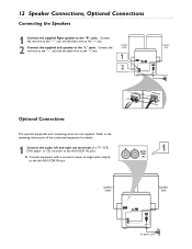
... ) R L AUX/ CDR IN AM ANTENNA FM ANTENNA R+ L + SPEAKERS AC MAINS AC power cord speaker (right) speaker (left ) R L AUX/ CDR IN AM ANTENNA FM ANTENNA R+ L + SPEAKERS AC MAINS AC power cord Optional Connections The optional equipment and connecting wires are not ...1 AUX/ CDR G Connect equipment with a monaural output (a single audio output) IN to the "R" jacks. 12 Speaker Connections, Optional Connections Connecting the Speakers 1 Connect the supplied Right speaker to the left AUX/CDR IN jack. Connect the red wire to the "-" jack and the black wire to the...
... ) R L AUX/ CDR IN AM ANTENNA FM ANTENNA R+ L + SPEAKERS AC MAINS AC power cord speaker (right) speaker (left ) R L AUX/ CDR IN AM ANTENNA FM ANTENNA R+ L + SPEAKERS AC MAINS AC power cord Optional Connections The optional equipment and connecting wires are not ...1 AUX/ CDR G Connect equipment with a monaural output (a single audio output) IN to the "R" jacks. 12 Speaker Connections, Optional Connections Connecting the Speakers 1 Connect the supplied Right speaker to the left AUX/CDR IN jack. Connect the red wire to the "-" jack and the black wire to the...

User manual
Page 16
There are three settings. 1 Press DBB. G The selected DBB level appears on the display. 1,2 INCREDIBLE SURROUND Incredible Surround magnifies the virtual distance between the front speakers for each DSC or VAC setting is automatically set. The DBB button lights up . 2 Adjust the JOG CONTROL (or press VAC on or off. 16 ...
There are three settings. 1 Press DBB. G The selected DBB level appears on the display. 1,2 INCREDIBLE SURROUND Incredible Surround magnifies the virtual distance between the front speakers for each DSC or VAC setting is automatically set. The DBB button lights up . 2 Adjust the JOG CONTROL (or press VAC on or off. 16 ...

User manual
Page 27
... the demo stops. The timer is no sound. • Adust the volume. • Disconnect the headphones. • Check the speaker connections. Reset the clock and timer. Some lights are reversed. • Check speaker connections and location. Press and hold STOP 7 until moisture has cleared from the lens. There is not working. •...
... the demo stops. The timer is no sound. • Adust the volume. • Disconnect the headphones. • Check the speaker connections. Reset the clock and timer. Some lights are reversed. • Check speaker connections and location. Press and hold STOP 7 until moisture has cleared from the lens. There is not working. •...
User manual
Page 28
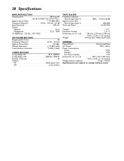
... total W 2X140 W RMS(1)/2X110 W FTC(1) Signal-to-Noise Ratio 75 dBA (IEC) Frequency Response 50 Hz - 20 kHz / ±3 dB Input Sensitivity 500 mV Output Speakers 6 Ω Headphones 32 Ω - 1000 (1) (6Ω60 Hz - 125 kHz, 10% THD) CD PLAYER SECTION Programmable Tracks 40 Frequency Response 20 Hz - 20 kHz Signal... / 60 Hz Power Consumption Active 175W Standby 25W Eco Power Standby 1W Dimensions (w x h x d 240 x 310 x 290 (mm 9.45 x 12.20 x 11.42 (inches) Weight (without speakers 9.0 kg / 19.8 lbs Specifications are subject to change without notice.
... total W 2X140 W RMS(1)/2X110 W FTC(1) Signal-to-Noise Ratio 75 dBA (IEC) Frequency Response 50 Hz - 20 kHz / ±3 dB Input Sensitivity 500 mV Output Speakers 6 Ω Headphones 32 Ω - 1000 (1) (6Ω60 Hz - 125 kHz, 10% THD) CD PLAYER SECTION Programmable Tracks 40 Frequency Response 20 Hz - 20 kHz Signal... / 60 Hz Power Consumption Active 175W Standby 25W Eco Power Standby 1W Dimensions (w x h x d 240 x 310 x 290 (mm 9.45 x 12.20 x 11.42 (inches) Weight (without speakers 9.0 kg / 19.8 lbs Specifications are subject to change without notice.
User manual
Page 29
... 17 setting the clock 24 setting the timer 25 setup 11 shuffle 19 shuffle button 7 sleep button 7 sleep timer 26 sound options 15 source buttons 7 speaker connections 12 specifications 28 standby y button 7 stop 7 button 7, 14 table of contents 3 tape playback 22 timer 25 timer on /off button 7 tuning to radio stations...
... 17 setting the clock 24 setting the timer 25 setup 11 shuffle 19 shuffle button 7 sleep button 7 sleep timer 26 sound options 15 source buttons 7 speaker connections 12 specifications 28 standby y button 7 stop 7 button 7, 14 table of contents 3 tape playback 22 timer 25 timer on /off button 7 tuning to radio stations...

Quick start guide
Page 1
...remote control. Quick Use Guide Use this simple and quick way to listen to your favorite CD, cassette, or radio station. 1C TO CONNECT YOUR FWC555 MINI HI-FI SYSTEM FOLLOW THESE STEPS: 1 ANTENNA CONNECTIONS A Connect the supplied AM loop antenna to see the "Plug and Play" section on the... to the "+" jack. 3 FINAL PREPARATION A Insert two (2) AA batteries into an outlet. AM loop antenna 1A 1B FM wire antenna speaker (right) 2A AUX/ CDR IN AM ANTENNA FM ANTENNA R+ L + SPEAKERS 2B AC MAINS speaker (left) 3B 3B AC power cord HELPFUL HINTS • Be sure to the AM ANTENNA jacks.
...remote control. Quick Use Guide Use this simple and quick way to listen to your favorite CD, cassette, or radio station. 1C TO CONNECT YOUR FWC555 MINI HI-FI SYSTEM FOLLOW THESE STEPS: 1 ANTENNA CONNECTIONS A Connect the supplied AM loop antenna to see the "Plug and Play" section on the... to the "+" jack. 3 FINAL PREPARATION A Insert two (2) AA batteries into an outlet. AM loop antenna 1A 1B FM wire antenna speaker (right) 2A AUX/ CDR IN AM ANTENNA FM ANTENNA R+ L + SPEAKERS 2B AC MAINS speaker (left) 3B 3B AC power cord HELPFUL HINTS • Be sure to the AM ANTENNA jacks.


