
WXC3010 User Guide
Page 1
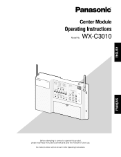
... in this manual for future use. Center Module Operating Instructions WX-C3010 Model No. ENGLISH FRANÇAIS AUX IN AUX SP TALK PAGE BEEP ECHDONCRANLCEEVLELELR RYGOEEFRLDFELEONWLOMOMFAWDFX INSTALL PREV SYSTEM SEL LPAONDTSEUXRASPELEOMLLWOAEENCTREET SETTING SPOUTSIDE NEXT MIC SP AUX MIC BEEP APUODSIO STPEEAEMD DAOOBYNP/E:NDEEIAGPRYHATTIOSNOOPUANLTL:EDSSVIADEYEELTTIONVVGE/DRERTIDE RELTE/PASE COTNETLREOPLHOONUET ID REGISTRATION ON 1SE2LECT GRSDETEEALARTYTER REC DOWNVOLUME PHLEAAYDBSAECTK UP AUXDESTINATION HEADSET POWER TALK PAGE...
... in this manual for future use. Center Module Operating Instructions WX-C3010 Model No. ENGLISH FRANÇAIS AUX IN AUX SP TALK PAGE BEEP ECHDONCRANLCEEVLELELR RYGOEEFRLDFELEONWLOMOMFAWDFX INSTALL PREV SYSTEM SEL LPAONDTSEUXRASPELEOMLLWOAEENCTREET SETTING SPOUTSIDE NEXT MIC SP AUX MIC BEEP APUODSIO STPEEAEMD DAOOBYNP/E:NDEEIAGPRYHATTIOSNOOPUANLTL:EDSSVIADEYEELTTIONVVGE/DRERTIDE RELTE/PASE COTNETLREOPLHOONUET ID REGISTRATION ON 1SE2LECT GRSDETEEALARTYTER REC DOWNVOLUME PHLEAAYDBSAECTK UP AUXDESTINATION HEADSET POWER TALK PAGE...

WXC3010 User Guide
Page 2
... not installed and used in conjunction with the instruction manual, may cause undesired operation. FCC Warning: This equipment complies with the limits for uncontrolled equipment and meets the FCC radio frequency (RF) Exposure Guidelines in the literature accompanying the appliance. 2 For U.S.A. REFER SERVICING TO QUALIFIED SERVICE PERSONNEL. FEDERAL COMMUNICATIONS COMMISSION INTERFERENCE STATEMENT For U.S.A. This equipment should note the model number and serial number...
... not installed and used in conjunction with the instruction manual, may cause undesired operation. FCC Warning: This equipment complies with the limits for uncontrolled equipment and meets the FCC radio frequency (RF) Exposure Guidelines in the literature accompanying the appliance. 2 For U.S.A. REFER SERVICING TO QUALIFIED SERVICE PERSONNEL. FEDERAL COMMUNICATIONS COMMISSION INTERFERENCE STATEMENT For U.S.A. This equipment should note the model number and serial number...

WXC3010 User Guide
Page 3
... use by qualified service per- To reduce the risk of electric shock do not perform any interference, including interference that is recyclable powers the product you are for this radio equipment is incorrectly replaced. tective earthing connection. • The mains plug or an appliance coupler shall remain readily operable. • To reduce the risk of explosion if battery is listed...
... use by qualified service per- To reduce the risk of electric shock do not perform any interference, including interference that is recyclable powers the product you are for this radio equipment is incorrectly replaced. tective earthing connection. • The mains plug or an appliance coupler shall remain readily operable. • To reduce the risk of explosion if battery is listed...
WXC3010 User Guide
Page 6
... Panasonic WX-C3010 Series System Parts and Accessories 16 Major Operating Controls and Their Functions 17 Installations/Connections ...19 I Installation procedures ...19 I Preparations ...19 I Installation of center modules on the wall 19 I Wiring to the center modules ...20 I Clamping the Power Plug and Power Cord 21 I Basic Connection ...22 I POS (Point of sales)-System Connection 23 I Double-Drive-Thru Connection ...24 I ID registration for follower units ...25 I Installed System Setting ...26 G Setup operation for AUX SP (Auxiliary Speaker...
... Panasonic WX-C3010 Series System Parts and Accessories 16 Major Operating Controls and Their Functions 17 Installations/Connections ...19 I Installation procedures ...19 I Preparations ...19 I Installation of center modules on the wall 19 I Wiring to the center modules ...20 I Clamping the Power Plug and Power Cord 21 I Basic Connection ...22 I POS (Point of sales)-System Connection 23 I Double-Drive-Thru Connection ...24 I ID registration for follower units ...25 I Installed System Setting ...26 G Setup operation for AUX SP (Auxiliary Speaker...
WXC3010 User Guide
Page 7
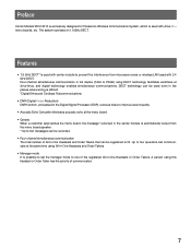
...* recorded in the center module is automatically output from microwave ovens or wireless LAN used with drive-thru menu boards, etc. Preface Center Module WX-C3010 is exclusively designed for Panasonic Wireless Communication System, which is used even in the places where wiring is difficult. *Digital Enhanced Cordless Telecommunications • DNR (Digital Noise Reduction) DNR function, processed in the Digital Signal Processor (DSP), reduces noise to improve sound...
...* recorded in the center module is automatically output from microwave ovens or wireless LAN used with drive-thru menu boards, etc. Preface Center Module WX-C3010 is exclusively designed for Panasonic Wireless Communication System, which is used even in the places where wiring is difficult. *Digital Enhanced Cordless Telecommunications • DNR (Digital Noise Reduction) DNR function, processed in the Digital Signal Processor (DSP), reduces noise to improve sound...
WXC3010 User Guide
Page 9
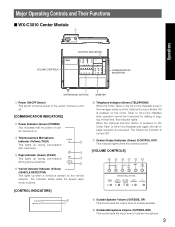
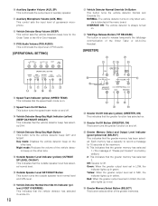
... team mode is recovered. The Telephone Indicator is sensed by the vehicle detector. VEHICLE DETECTOR t t Vehicle Detector Indicator (Yellow) (VEHICLE DETECTOR) This lights up when a vehicle is turned OFF. o Outside Microphone Volume (OUTSIDE, MIC) This control sets the input level of outside speaker. Major Operating Controls and Their Functions I WX-C3010 Center Module q Operations VOLUME CONTROLS CONTROL INDICATORS COMMUNICATION INDICATORS OPERATIONAL SETTING GREETER q Power ON/OFF Switch This switch turns the power of the center module on...
... team mode is recovered. The Telephone Indicator is sensed by the vehicle detector. VEHICLE DETECTOR t t Vehicle Detector Indicator (Yellow) (VEHICLE DETECTOR) This lights up when a vehicle is turned OFF. o Outside Microphone Volume (OUTSIDE, MIC) This control sets the input level of outside speaker. Major Operating Controls and Their Functions I WX-C3010 Center Module q Operations VOLUME CONTROLS CONTROL INDICATORS COMMUNICATION INDICATORS OPERATIONAL SETTING GREETER q Power ON/OFF Switch This switch turns the power of the center module on...
WXC3010 User Guide
Page 10
... button is detected at the maximum. 1: This indicates that the greeter memory has selected 1. (The message of "Please pull forward" is a factory default.) 2: This indicates that the greeter memory has selected 2. Night mode: Reduces the volume of the vehicle detector beep on the other lane. !0 Auxiliary Speaker Volume (AUX, SP) This control sets the output level of auxiliary speaker. !1 Auxiliary Microphone Volume (AUX, MIC...
... button is detected at the maximum. 1: This indicates that the greeter memory has selected 1. (The message of "Please pull forward" is a factory default.) 2: This indicates that the greeter memory has selected 2. Night mode: Reduces the volume of the vehicle detector beep on the other lane. !0 Auxiliary Speaker Volume (AUX, SP) This control sets the output level of auxiliary speaker. !1 Auxiliary Microphone Volume (AUX, MIC...
WXC3010 User Guide
Page 12
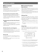
... Headset (WX-H3050). G Communications with any time by customers. Lastly, press the Power ON/OFF switch of the center module to turn the power supply ON. I Basic Operation G Power ON Press the Power ON/OFF Switch of the center module to turn its power supply OFF. Press the SPEED TEAM button of Auto Talk Lock Mode setup, refer to PTP, it operates by pressing the PAGE button. 4. Operating Procedures I Convenient Functions G Auto Talk Lock When a customer approaches the menu...
... Headset (WX-H3050). G Communications with any time by customers. Lastly, press the Power ON/OFF switch of the center module to turn the power supply ON. I Basic Operation G Power ON Press the Power ON/OFF Switch of the center module to turn its power supply OFF. Press the SPEED TEAM button of Auto Talk Lock Mode setup, refer to PTP, it operates by pressing the PAGE button. 4. Operating Procedures I Convenient Functions G Auto Talk Lock When a customer approaches the menu...
WXC3010 User Guide
Page 13
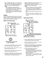
... Greeter Output Auxiliary Speaker Button of recording message] q Greeter On/Off Button e Greeter Record Button GREETER ON START REC DELAY SELECT 12 HEADSET PLAYBACK VOLUME DOWN UP DESTINATION AUX HEADSET w Greeter Memory Select Button 5. Press the PAGE button at the PAGE LOCK setting. If TALK is attempted with the Order Taker or the Allin-One Headset, a voice prompt of the Center Module. G Greeter When the customer approaches the menu...
... Greeter Output Auxiliary Speaker Button of recording message] q Greeter On/Off Button e Greeter Record Button GREETER ON START REC DELAY SELECT 12 HEADSET PLAYBACK VOLUME DOWN UP DESTINATION AUX HEADSET w Greeter Memory Select Button 5. Press the PAGE button at the PAGE LOCK setting. If TALK is attempted with the Order Taker or the Allin-One Headset, a voice prompt of the Center Module. G Greeter When the customer approaches the menu...
WXC3010 User Guide
Page 14
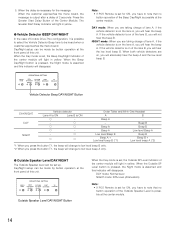
... indicator will light in yellow. G Outside Speaker Level DAY/NIGHT The Outside Speaker level can be set for the message When the customer approaches the menu board, the message is assumed and this unit. 5. When the Beep Day/Night button is pressed, the Night mode is output after a delay of the Center Module. Day/Night setup can be made by button operation at the center module.
... indicator will light in yellow. G Outside Speaker Level DAY/NIGHT The Outside Speaker level can be set for the message When the customer approaches the menu board, the message is assumed and this unit. 5. When the Beep Day/Night button is pressed, the Night mode is output after a delay of the Center Module. Day/Night setup can be made by button operation at the center module.
WXC3010 User Guide
Page 15
... Headset side, the Outside Speaker and the Outside Microphone are turned ON at the menu board. When the Talk button is set, the V/D Override indicator of the center module will disappear. When setting the normal position, Auto Talk Lock mode is assumed and this unit. When the Override On mode is pressed on , a beep tone is set up. When the vehicle leaves, the vehicle detector turns off. OPERATIONAL SETTING...
... Headset side, the Outside Speaker and the Outside Microphone are turned ON at the menu board. When the Talk button is set, the V/D Override indicator of the center module will disappear. When setting the normal position, Auto Talk Lock mode is assumed and this unit. When the Override On mode is pressed on , a beep tone is set up. When the vehicle leaves, the vehicle detector turns off. OPERATIONAL SETTING...
WXC3010 User Guide
Page 16
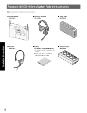
... used for WX-H3050 and WXT3020 • WX-B3030 and 1UF653450RMDSP are same models. Panasonic WX-C3010 Series System Parts and Accessories Note: Illustrations may differ from actual products. I Center Module WX-C3010 I All-in-One Headset WX-H3050 I Order Taker WX-T3020 AUX SP AUX IN TALK PAGE BEEP ECHDONCRANLCEEVLELELR RYGOEERFLDFELEONWLOMOMFAWDFX INSTALL PREV SYSTEM SEL LPAODNTSUEXRASPELEOMLLWAOEENCTREET SETTING SPOUTSIDE NEXT MIC...
... used for WX-H3050 and WXT3020 • WX-B3030 and 1UF653450RMDSP are same models. Panasonic WX-C3010 Series System Parts and Accessories Note: Illustrations may differ from actual products. I Center Module WX-C3010 I All-in-One Headset WX-H3050 I Order Taker WX-T3020 AUX SP AUX IN TALK PAGE BEEP ECHDONCRANLCEEVLELELR RYGOEERFLDFELEONWLOMOMFAWDFX INSTALL PREV SYSTEM SEL LPAODNTSUEXRASPELEOMLLWAOEENCTREET SETTING SPOUTSIDE NEXT MIC...

WXC3010 User Guide
Page 17
... provided through the auxiliary speaker. !3 Echo Canceller Effect Level Control Indicator (ECHO CANCELLER) The removal rate of the page 27 relationship between noise reduction level and quality. Major Operating Controls and Their Functions qw e Installation & Connections r r INSTALLED SYSTEM SETTING t ID REGISTRATION t y q AC Inlet w Power On/Off Switch e Through-hole r Antenna t Mounting Hole y Terminal Board Cover [INSTALLED SYSTEM SETTING] The following buttons should be . OFF: Off...
... provided through the auxiliary speaker. !3 Echo Canceller Effect Level Control Indicator (ECHO CANCELLER) The removal rate of the page 27 relationship between noise reduction level and quality. Major Operating Controls and Their Functions qw e Installation & Connections r r INSTALLED SYSTEM SETTING t ID REGISTRATION t y q AC Inlet w Power On/Off Switch e Through-hole r Antenna t Mounting Hole y Terminal Board Cover [INSTALLED SYSTEM SETTING] The following buttons should be . OFF: Off...
WXC3010 User Guide
Page 19
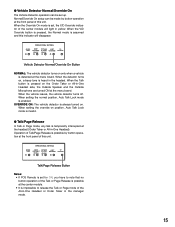
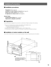
... COTNETLREOPLHOONUET ID REGISTRATION ON 1SE2LECT GRSDETEEALRATYTER REC DOWNVOLUME PHLEAAYDBSAECTK UP AUXDESTINATION HEADSET POWER TALK PAGE DVEETHEICCTLOER 386 mm {15-1/4"} 225 mm {8-7/8"} 25 mm {1"} Use the dents at the top or bottom of center module for follower units (Refer to page 25.) [System Setup] Installed System Setting (Refer to page 26.) Adjustments to adequate sound levels I Installation procedures Preparations (Refer to page 19...
... COTNETLREOPLHOONUET ID REGISTRATION ON 1SE2LECT GRSDETEEALRATYTER REC DOWNVOLUME PHLEAAYDBSAECTK UP AUXDESTINATION HEADSET POWER TALK PAGE DVEETHEICCTLOER 386 mm {15-1/4"} 225 mm {8-7/8"} 25 mm {1"} Use the dents at the top or bottom of center module for follower units (Refer to page 25.) [System Setup] Installed System Setting (Refer to page 26.) Adjustments to adequate sound levels I Installation procedures Preparations (Refer to page 19...
WXC3010 User Guide
Page 20
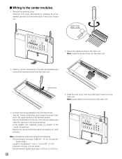
... the upper surface of the wiring material and insert the cable tip in the slot as illustrated and remove the terminal socket from the bottom and mount it on the main unit. Peel off the sheath from the tip of the terminal socket. Note: Surely attach the front cover to the following. I Wiring to the center modules 1.
... the upper surface of the wiring material and insert the cable tip in the slot as illustrated and remove the terminal socket from the bottom and mount it on the main unit. Peel off the sheath from the tip of the terminal socket. Note: Surely attach the front cover to the following. I Wiring to the center modules 1.
WXC3010 User Guide
Page 21
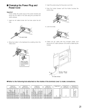
... following lists attached on the inside of the terminal cover to the backward by fastening the screws. Insert an AC cable holder into the power cord inlet. 4. Insert the power plug into the hole under the AC inlet. 3. AC cable holder 2. Slide the holder to make connections. Push the holder forward until the holder touches the power plug. 2 3 5. Lock the holder. CONNECTOR...
... following lists attached on the inside of the terminal cover to the backward by fastening the screws. Insert an AC cable holder into the power cord inlet. 4. Insert the power plug into the hole under the AC inlet. 3. AC cable holder 2. Slide the holder to make connections. Push the holder forward until the holder touches the power plug. 2 3 5. Lock the holder. CONNECTOR...
WXC3010 User Guide
Page 25
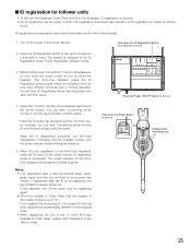
... hear "Connecting center module B" and the lane indicator will blink yellow. * Press the T2 button (at double-drive-thru), for the center module. I ID registration for follower units • To talk with the headsets (Order Taker and All-in-One Headset), ID registration is required. • For ID registration, set the center module in normal operation. Turn on the All-in -One Headset searches for other center modules. The...
... hear "Connecting center module B" and the lane indicator will blink yellow. * Press the T2 button (at double-drive-thru), for the center module. I ID registration for follower units • To talk with the headsets (Order Taker and All-in-One Headset), ID registration is required. • For ID registration, set the center module in normal operation. Turn on the All-in -One Headset searches for other center modules. The...
WXC3010 User Guide
Page 26
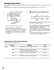
... the style of the PREV/NEXT button and the SEL button. Indicator of installation work, system setup shall be made according to the equipment to the auxiliary speakers. * The sound of the center module. 2. TALK PAGE TALK audio is output to be connected and the operation mode. OFF No output No output No output No output 26 OFF: Lighting time is short and unlighting time is a reciprocal changeover between ON Select...
... the style of the PREV/NEXT button and the SEL button. Indicator of installation work, system setup shall be made according to the equipment to the auxiliary speakers. * The sound of the center module. 2. TALK PAGE TALK audio is output to be connected and the operation mode. OFF No output No output No output No output 26 OFF: Lighting time is short and unlighting time is a reciprocal changeover between ON Select...
WXC3010 User Guide
Page 31
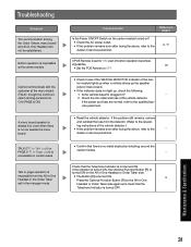
... and fuse of the cen- Cause/solution Reference pages Is the Power ON/OFF Switch on the center module turned on the All-in -One Headset or the Order Taker set for ON, part of button operation becomes impossible. 18 • Set the POS Remote to OFF. • Check to the qualified ser- Troubleshooting Symptom The communication among personnel is O.K (PAGE is OK) A menu board speaker...
... and fuse of the cen- Cause/solution Reference pages Is the Power ON/OFF Switch on the center module turned on the All-in -One Headset or the Order Taker set for ON, part of button operation becomes impossible. 18 • Set the POS Remote to OFF. • Check to the qualified ser- Troubleshooting Symptom The communication among personnel is O.K (PAGE is OK) A menu board speaker...
WXC3010 User Guide
Page 32
.... But, the Single Lane operation works well. • Check to see whether the power of them to comfortable level. - Note: Lower inbound audio setting may not be properly installed. • Be sure speaker and microphone are blinking after startup, and communication cannot be "LOW". • Set echo canceller level properly. each other Center Module is "MAX"(LED:RED)) 27 DNR may be OFF...
.... But, the Single Lane operation works well. • Check to see whether the power of them to comfortable level. - Note: Lower inbound audio setting may not be properly installed. • Be sure speaker and microphone are blinking after startup, and communication cannot be "LOW". • Set echo canceller level properly. each other Center Module is "MAX"(LED:RED)) 27 DNR may be OFF...


