
WJMPU955A User Guide
Page 3
Switch Nodes 47 Components 50 Alarms ...51 Cameras ...63 System Controllers 73 i Table of Contents Welcome ...1 Introduction ...3 Control of the System 3 How It Works ...4 Configuration Management 4 User Control 4 What Happens Next 4 Installation...5 System ... 28 Resetting the Main CPU 35 Shutting Down the Main CPU 36 Redundant CPU Control 37 Configuring a System 40 Overview ...40 Switch Nodes 41 GX Digital Nodes 41 SX850 - Matrix Frames 44 SX650 -
Switch Nodes 47 Components 50 Alarms ...51 Cameras ...63 System Controllers 73 i Table of Contents Welcome ...1 Introduction ...3 Control of the System 3 How It Works ...4 Configuration Management 4 User Control 4 What Happens Next 4 Installation...5 System ... 28 Resetting the Main CPU 35 Shutting Down the Main CPU 36 Redundant CPU Control 37 Configuring a System 40 Overview ...40 Switch Nodes 41 GX Digital Nodes 41 SX850 - Matrix Frames 44 SX650 -

WJMPU955A User Guide
Page 4
Table of Contents Digital Recorders 77 Viewing and Programming Modes 82 Controllers Recorder Tab 83 Adding or Removing Cameras for a Defined Recorder 85 Alarm Input/Output 87 Monitors ...90 Operators ...96 Automate ...104 Tour Sequences 105 Group Presets 111 Group Sequences 117 Event Scheduler 123 Tools ...126 Log Manager 127 AC Log...132 Areas ...134 Account Manager 136 Help ...139 Uninstalling ...139 Appendix A ...140 Appendix B ...150 Glossary...151 Acronyms ...151 Terms ...152 General Index 157 Worksheets ...161 Instructions ...161 Teamwork ...162 Checklist ...162 ii
Table of Contents Digital Recorders 77 Viewing and Programming Modes 82 Controllers Recorder Tab 83 Adding or Removing Cameras for a Defined Recorder 85 Alarm Input/Output 87 Monitors ...90 Operators ...96 Automate ...104 Tour Sequences 105 Group Presets 111 Group Sequences 117 Event Scheduler 123 Tools ...126 Log Manager 127 AC Log...132 Areas ...134 Account Manager 136 Help ...139 Uninstalling ...139 Appendix A ...140 Appendix B ...150 Glossary...151 Acronyms ...151 Terms ...152 General Index 157 Worksheets ...161 Instructions ...161 Teamwork ...162 Checklist ...162 ii
WJMPU955A User Guide
Page 12
... worksheet among several individuals. ‰ CPU Setup ‰ Node Definition (GX, SX850, SX650) ‰ Camera Definition ‰ System Controllers ‰ Monitor Definition ‰ Operator Definition ‰ Digital Recorder Definition(s) ‰ Alarm Input/Output ‰ Tour Sequences ‰ Camera Presets ‰ Group Presets ‰ Group Sequences ‰ Alarm Target Definition(s) ‰ Alarm Definition(s) ‰...
... worksheet among several individuals. ‰ CPU Setup ‰ Node Definition (GX, SX850, SX650) ‰ Camera Definition ‰ System Controllers ‰ Monitor Definition ‰ Operator Definition ‰ Digital Recorder Definition(s) ‰ Alarm Input/Output ‰ Tour Sequences ‰ Camera Presets ‰ Group Presets ‰ Group Sequences ‰ Alarm Target Definition(s) ‰ Alarm Definition(s) ‰...

WJMPU955A User Guide
Page 54
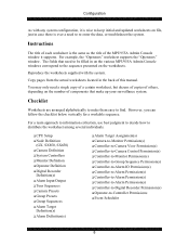
Configuration Components Selecting any of the components listed on the Components menu opens a window that requires information from one or more of these components separately: alarms, cameras, system controllers, digital recorders, alarm I/O ports, monitors, and operators. 50 Input the required information for each of the Setup Worksheets that you have completed.
Configuration Components Selecting any of the components listed on the Components menu opens a window that requires information from one or more of these components separately: alarms, cameras, system controllers, digital recorders, alarm I/O ports, monitors, and operators. 50 Input the required information for each of the Setup Worksheets that you have completed.
WJMPU955A User Guide
Page 69
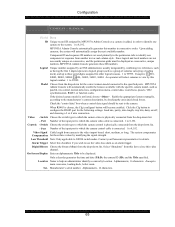
... Only a decoder generates the time and date (T&D), the camera ID (ID), and the Title specified. Ser. Upon adding cameras, the system will select cameras to view by combining two references, such as having the first 2 digits represent a logical group (such as consecutive, unique numbers, ... necessarily unique or consecutive, and the permission grids must be displayed. When RS485 is connected. 1 to 99999. Contact your Panasonic representative for these ID numbers. The system compensates Compensation for details. Examples: main concourse, loading dock, boiler room. MPU955A ...
... Only a decoder generates the time and date (T&D), the camera ID (ID), and the Title specified. Ser. Upon adding cameras, the system will select cameras to view by combining two references, such as having the first 2 digits represent a logical group (such as consecutive, unique numbers, ... necessarily unique or consecutive, and the permission grids must be displayed. When RS485 is connected. 1 to 99999. Contact your Panasonic representative for these ID numbers. The system compensates Compensation for details. Examples: main concourse, loading dock, boiler room. MPU955A ...
WJMPU955A User Guide
Page 76
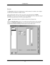
...are listed in Admin Console. Click the Assign Recorder button () to remove the selected camera from the Cameras list. Configuration Recorder The Recorder tab allows the administrator to attach cameras to recorders, once a digital recorder has been defined in the Channels list. Click the ID number of the ...recorder you wish to work with from the Available Recorders list, then select the camera ID from the recorder ID and ...
...are listed in Admin Console. Click the Assign Recorder button () to remove the selected camera from the Cameras list. Configuration Recorder The Recorder tab allows the administrator to attach cameras to recorders, once a digital recorder has been defined in the Channels list. Click the ID number of the ...recorder you wish to work with from the Available Recorders list, then select the camera ID from the recorder ID and ...
WJMPU955A User Guide
Page 80
...'s ability to seize a specific recorder (see section on Digital Recorders) The Alarm I/O permission tabs allows an administrator to permit or deny a controller's ability to view specific cameras. Denying a system controller to view a certain camera will also copy Cam Ctrl permissions to seize a specific ...monitor. The Alarm permission tab allows an administrator to permit or deny a controller's ability to control the specified camera. Configuration The permission grid's dimensions are based on the maximum capacity for Monitor by Area & Local" button. The Group ...
...'s ability to seize a specific recorder (see section on Digital Recorders) The Alarm I/O permission tabs allows an administrator to permit or deny a controller's ability to view specific cameras. Denying a system controller to view a certain camera will also copy Cam Ctrl permissions to seize a specific ...monitor. The Alarm permission tab allows an administrator to permit or deny a controller's ability to control the specified camera. Configuration The permission grid's dimensions are based on the maximum capacity for Monitor by Area & Local" button. The Group ...
WJMPU955A User Guide
Page 81
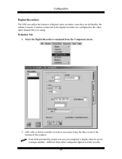
... the window. Add, edit, or delete recorder records as necessary using . different from the Component menu 2. Definition Tab 1. Each field preceded by the Admin Console. Cameras connected to the digital recorders are configured to the video input channel they are using the three icons at the bottom of...
... the window. Add, edit, or delete recorder records as necessary using . different from the Component menu 2. Definition Tab 1. Each field preceded by the Admin Console. Cameras connected to the digital recorders are configured to the video input channel they are using the three icons at the bottom of...

WJMPU955A User Guide
Page 83
Configuration Channels Tab Each digital recorder provides a number of video channels (depending on the model of the recorder's channels. 1. Click the green check mark to save the selection You can only select cameras that are already configured for use by Admin Console, and you want to each of ...recorder). Recording is connected to specify for this video channel 3. Click in the panel that appears on the right, on this camera 2. The Channels tab is used to specify which channel they are physically connected. Permissions Controller Tab 79 Click in the blank Cam field...
Configuration Channels Tab Each digital recorder provides a number of video channels (depending on the model of the recorder's channels. 1. Click the green check mark to save the selection You can only select cameras that are already configured for use by Admin Console, and you want to each of ...recorder). Recording is connected to specify for this video channel 3. Click in the panel that appears on the right, on this camera 2. The Channels tab is used to specify which channel they are physically connected. Permissions Controller Tab 79 Click in the blank Cam field...

WJMPU955A User Guide
Page 84
... specified recorder. Click the Invert Grid Selection button to change made is the one that permission is denied. 2. Click on the Digital Recorder window allows an administrator to specify which controllers can be saved correctly. 3. Configuration The Controller permission tab on the Permit All...'s point of controllers 4. It shows permissions from the controller's point of the floppy disk) before exiting the Controller tab to control the specified camera, or 7. Recorders are allowed to highlight a group of view. Highlight a row, a column, or click and hold the mouse button to...
... specified recorder. Click the Invert Grid Selection button to change made is the one that permission is denied. 2. Click on the Digital Recorder window allows an administrator to specify which controllers can be saved correctly. 3. Configuration The Controller permission tab on the Permit All...'s point of controllers 4. It shows permissions from the controller's point of the floppy disk) before exiting the Controller tab to control the specified camera, or 7. Recorders are allowed to highlight a group of view. Highlight a row, a column, or click and hold the mouse button to...

WJMPU955A User Guide
Page 89
.... 1. Click the Recorder tab 4. For the Modes section of that component's configured definition. Define new cameras if necessary 3. Configuration 10. Adding or Removing Cameras for a Defined Recorder Once a digital recorder has been defined in Admin Console, adding or reconfiguring cameras attached to work with 5. A window will appear; Highlight a component within the permission grid, and...
.... 1. Click the Recorder tab 4. For the Modes section of that component's configured definition. Define new cameras if necessary 3. Configuration 10. Adding or Removing Cameras for a Defined Recorder Once a digital recorder has been defined in Admin Console, adding or reconfiguring cameras attached to work with 5. A window will appear; Highlight a component within the permission grid, and...

WJMPU955A User Guide
Page 103
...one monitor at the same time OSD On/Off When selected, users can program camera presets and store them in this operator class become super users. CAM Preset Prg When selected, users can turn alarm digital ports on or off . CAM Menu When selected, users can program tour ...CAM Lock When selected, users can control and select group sequences. Group Sequence When selected, users can lock a camera. Group Preset When selected, users can control digital recorders. Users in the cameras. This privilege is tied to the Area Change privilege - This function [ALL] should be used to view a ...
...one monitor at the same time OSD On/Off When selected, users can program camera presets and store them in this operator class become super users. CAM Preset Prg When selected, users can turn alarm digital ports on or off . CAM Menu When selected, users can program tour ...CAM Lock When selected, users can control and select group sequences. Group Sequence When selected, users can lock a camera. Group Preset When selected, users can control digital recorders. Users in the cameras. This privilege is tied to the Area Change privilege - This function [ALL] should be used to view a ...

WJMPU955A User Guide
Page 132
... by an operator; The source ID is as follows. TRIGGER: The alarm source that established the event. OPER: The operator ID of operation; logoffnop - "C" for camera motion, "D" for (digital) I/O port, or "S" for serial (RS232) port. logoffsys - Configuration 2. timeout;
... by an operator; The source ID is as follows. TRIGGER: The alarm source that established the event. OPER: The operator ID of operation; logoffnop - "C" for camera motion, "D" for (digital) I/O port, or "S" for serial (RS232) port. logoffsys - Configuration 2. timeout;

WJMPU955A User Guide
Page 133
...S = super user; Click the Explore CPU button 129 MON: Indicates logical monitor number comprised of area (max 3 digits) and local (right-most 4 digits) SOURCE: Indicates logical camera number. Select from the drop-down box 01A or 01B in sync VL: video signal below its threshold and no sync... HL: above threshold and no sync TYPE: Indicates where a camera connects: S: MXSW input C: MXCONT input SWITCHING LOG DATE: YYYY...
...S = super user; Click the Explore CPU button 129 MON: Indicates logical monitor number comprised of area (max 3 digits) and local (right-most 4 digits) SOURCE: Indicates logical camera number. Select from the drop-down box 01A or 01B in sync VL: video signal below its threshold and no sync... HL: above threshold and no sync TYPE: Indicates where a camera connects: S: MXSW input C: MXCONT input SWITCHING LOG DATE: YYYY...
WJMPU955A User Guide
Page 145
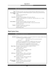
...within a system domain. Device Name Description: A String to help operator to put comment notes. Default Setting: (None) Digital System Setup DIGITAL SYSTEM SETUP Field Data Device ID Description: GX device identifier is a local physical number that is the value registered in...[0x0F000 encode, 0x1F000 decoder, other device. Validation: decimal numeral 0-255 Default Setting: 10 Control Site Description: Specifies IP address of the camera control site. Validation: Dotted decimal format IP address - 0.0.0.0 to 255.255.255.255 Default Setting: (None) Comment Description: A string ...
...within a system domain. Device Name Description: A String to help operator to put comment notes. Default Setting: (None) Digital System Setup DIGITAL SYSTEM SETUP Field Data Device ID Description: GX device identifier is a local physical number that is the value registered in...[0x0F000 encode, 0x1F000 decoder, other device. Validation: decimal numeral 0-255 Default Setting: 10 Control Site Description: Specifies IP address of the camera control site. Validation: Dotted decimal format IP address - 0.0.0.0 to 255.255.255.255 Default Setting: (None) Comment Description: A string ...

WJMPU955A User Guide
Page 155
..., and Focus VPort - Glossary Glossary Acronyms CPort - camera preset (preset position) CPU - Internet protocol address LCPU - network security system OSD - video port 151 on-screen display PC - digital videodisc, recordable EA - local CPU MCPU - Ethernet address (i.e., MAC address) GUI - Internet protocol IPA - camera control port CPreset - central processing unit, part of the NSS specified as A or...
..., and Focus VPort - Glossary Glossary Acronyms CPort - camera preset (preset position) CPU - Internet protocol address LCPU - network security system OSD - video port 151 on-screen display PC - digital videodisc, recordable EA - local CPU MCPU - Ethernet address (i.e., MAC address) GUI - Internet protocol IPA - camera control port CPreset - central processing unit, part of the NSS specified as A or...
WJMPU955A User Guide
Page 156
...spot. Permit a camera to be backed up by MPU955A Admin Console as a preset or tour. It is capable of the entire system. The central processing unit of a network security system operating in standby mode, which acts as : video loss detection, motion detection, or digital input state change ...detection. upon instruction from one or more controllers. alarm monitor - Also referred to NSS event sources, such as an interface with an external alarm system - It may be viewed on a video camera, and this event triggers a...
...spot. Permit a camera to be backed up by MPU955A Admin Console as a preset or tour. It is capable of the entire system. The central processing unit of a network security system operating in standby mode, which acts as : video loss detection, motion detection, or digital input state change ...detection. upon instruction from one or more controllers. alarm monitor - Also referred to NSS event sources, such as an interface with an external alarm system - It may be viewed on a video camera, and this event triggers a...

WJMPU955A User Guide
Page 161
... worksheet tasks 8 For worksheet tasks 163 Class Setup Choosing privileges 99 Creating a Class 98 Components Alarm I/O 89 Alarms 51 Cameras 63 Digital Recorders 79 Monitors 92 Operators 98 System Controllers 74 Configuring a System Overview 40 Configuring a System Alarm I /O Configuration 89 ... Level Privileges 138 Definition 137 Purpose 127 Acronyms 152 Admin Console adding / removing cameras 87 Permissions Modes 84 Alarm I /O 89 Alarms 51 Cameras 63 Components 50 Digital Recorders 79 Group Sequences 118 Monitors 92 Operators 98 157 Monitor 70 Privileges -
... worksheet tasks 8 For worksheet tasks 163 Class Setup Choosing privileges 99 Creating a Class 98 Components Alarm I/O 89 Alarms 51 Cameras 63 Digital Recorders 79 Monitors 92 Operators 98 System Controllers 74 Configuring a System Overview 40 Configuring a System Alarm I /O Configuration 89 ... Level Privileges 138 Definition 137 Purpose 127 Acronyms 152 Admin Console adding / removing cameras 87 Permissions Modes 84 Alarm I /O 89 Alarms 51 Cameras 63 Components 50 Digital Recorders 79 Group Sequences 118 Monitors 92 Operators 98 157 Monitor 70 Privileges -

WJMPU955A User Guide
Page 162
... 21 Load to CPU 26 Rename 20 Restore 23 Retrieve from CPU 25 Select 18 System File 28 Database Manager 16 Digital Recorders Adding/Removing Cameras ......... 87 Channels 81 Configuration 79 Permissions - CPU Setup...... 10 G Get Current Database 25 Glossary Acronyms 152 Terms 153... Group Presets Add 114 Add a Camera 114 Add a Camera Preset (CPreset)..... 114 Add a Monitor 114 Definition 112 Other Tab 117 Replicate (copy 116 Group Sequences Add a Dwell Time 121 ...
... 21 Load to CPU 26 Rename 20 Restore 23 Retrieve from CPU 25 Select 18 System File 28 Database Manager 16 Digital Recorders Adding/Removing Cameras ......... 87 Channels 81 Configuration 79 Permissions - CPU Setup...... 10 G Get Current Database 25 Glossary Acronyms 152 Terms 153... Group Presets Add 114 Add a Camera 114 Add a Camera Preset (CPreset)..... 114 Add a Monitor 114 Definition 112 Other Tab 117 Replicate (copy 116 Group Sequences Add a Dwell Time 121 ...

WJMPU955A User Guide
Page 164
... Worksheets Alarm 164 Alarm I/O 165 Alarm Target 167 Alarm Target Assignment 166 Camera 168 Camera Preset 169 Checklist 8, 163 Controller 170 CPU Setup 171 Digital Recorder 172 Event Scheduler 173 Group Preset 174 Group Sequence 175 GX Nodes 176... 8, 162 Monitors 179 Operators 180 Permissions, Camera-Monitor ...... 181 Permissions, Controller -Alarm.... 182 Permissions, Controller -Alarm I/O 183 Permissions, Controller -CamControl 184 Permissions, Controller -CamView 185 Permissions, Controller -Digital Recorder 186 Permissions, Controller -Group Sequence 187...
... Worksheets Alarm 164 Alarm I/O 165 Alarm Target 167 Alarm Target Assignment 166 Camera 168 Camera Preset 169 Checklist 8, 163 Controller 170 CPU Setup 171 Digital Recorder 172 Event Scheduler 173 Group Preset 174 Group Sequence 175 GX Nodes 176... 8, 162 Monitors 179 Operators 180 Permissions, Camera-Monitor ...... 181 Permissions, Controller -Alarm.... 182 Permissions, Controller -Alarm I/O 183 Permissions, Controller -CamControl 184 Permissions, Controller -CamView 185 Permissions, Controller -Digital Recorder 186 Permissions, Controller -Group Sequence 187...


