
Operating Instructions
Page 11
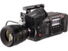
...to each button. Pressing a button performs the assigned function. 3 Focus hook/focus mark < > Indicate the focal plane of the MOS sensor. 4 button Press this when the camera is in use. Press this in red during recording. 5 switch Switch for changing the electronic shutter... Switch for changing the white balance. 11 Fan inlet Fan inlet for changing the EXPOSURE INDEX (gain). 7 Accessory mounting holes For attaching accessories. ffMounting hole size 7 8 9 10 11 - 11 - Right side 1 6 2 3 4 5 1 Accessory mounting holes For attaching accessories. Camera module Left side Chapter 2...
...to each button. Pressing a button performs the assigned function. 3 Focus hook/focus mark < > Indicate the focal plane of the MOS sensor. 4 button Press this when the camera is in use. Press this in red during recording. 5 switch Switch for changing the electronic shutter... Switch for changing the white balance. 11 Fan inlet Fan inlet for changing the EXPOSURE INDEX (gain). 7 Accessory mounting holes For attaching accessories. ffMounting hole size 7 8 9 10 11 - 11 - Right side 1 6 2 3 4 5 1 Accessory mounting holes For attaching accessories. Camera module Left side Chapter 2...

Operating Instructions
Page 12
...measuring the accurate focal length from the camera module. 4 Accessory mounting holes For attaching accessories. It provides a maximum current of light entering the MOS sensor to 1/64. 5 Lens lever After mounting the lens to the lens mount, tighten the lever to 1/16. : Reduces the amount of 1 A.... the lens. 6 Mount cap Attach the cap when the lens is not mounted. - 12 - Chapter 2 Description of the MOS sensor. Do not block this button. ffMounting hole size -- 1/4‑20 UNC (screw length 5.5 mm or shorter) 5 USER button () User-selected functions can be assigned to the viewfinder...
...measuring the accurate focal length from the camera module. 4 Accessory mounting holes For attaching accessories. It provides a maximum current of light entering the MOS sensor to 1/64. 5 Lens lever After mounting the lens to the lens mount, tighten the lever to 1/16. : Reduces the amount of 1 A.... the lens. 6 Mount cap Attach the cap when the lens is not mounted. - 12 - Chapter 2 Description of the MOS sensor. Do not block this button. ffMounting hole size -- 1/4‑20 UNC (screw length 5.5 mm or shorter) 5 USER button () User-selected functions can be assigned to the viewfinder...

Operating Instructions
Page 18
...Displays the camera menu screen. 3 button Displays the viewfinder menu screen. 4 Jog dial Operation dial. This connects to each button. The eye sensor may be assigned to the camera module (optional). Turn this attached. - 18 - Used for setting, moving, and selecting in the viewfinder menu.... 2 Connection terminal Terminal for connecting the supplied cable. This can be hidden. 6 Visibility adjustment ring Ring which enlarges/reduces the size of Parts - Use the camera with this ring while pressing and holding the upper button. 7 Eye cup Front 1 2 1 Tally LED ...
...Displays the camera menu screen. 3 button Displays the viewfinder menu screen. 4 Jog dial Operation dial. This connects to each button. The eye sensor may be assigned to the camera module (optional). Turn this attached. - 18 - Used for setting, moving, and selecting in the viewfinder menu.... 2 Connection terminal Terminal for connecting the supplied cable. This can be hidden. 6 Visibility adjustment ring Ring which enlarges/reduces the size of Parts - Use the camera with this ring while pressing and holding the upper button. 7 Eye cup Front 1 2 1 Tally LED ...

