
TH65PF9UK User Guide
Page 4
...after-image 31 SIDE BAR ADJUST 32 Reduces power consumption 33 Customizing the Input labels 33 SET UP for MULTI DISPLAY 34 How to setup MULTI DISPLAY 34 How to the Panasonic family of customers. Dear Panasonic Customer Welcome to set in the space provided on the rear cover ... obtain maximum benefit from your set the Display location number for each Plasma Display 35 SEAM HIDES VIDEO Setting 36 ID Remote Control Function 36 SET UP for Input Signals 37 COMPONENT / RGB IN SELECT 37 3D Y/C FILTER 37 COLOR SYSTEM / Panasonic AUTO 38 3:2 PULLDOWN / VIDEO NR 38 SYNC 39 H-FREQ. (...
...after-image 31 SIDE BAR ADJUST 32 Reduces power consumption 33 Customizing the Input labels 33 SET UP for MULTI DISPLAY 34 How to setup MULTI DISPLAY 34 How to the Panasonic family of customers. Dear Panasonic Customer Welcome to set in the space provided on the rear cover ... obtain maximum benefit from your set the Display location number for each Plasma Display 35 SEAM HIDES VIDEO Setting 36 ID Remote Control Function 36 SET UP for Input Signals 37 COMPONENT / RGB IN SELECT 37 3D Y/C FILTER 37 COLOR SYSTEM / Panasonic AUTO 38 3:2 PULLDOWN / VIDEO NR 38 SYNC 39 H-FREQ. (...

TH65PF9UK User Guide
Page 6
... through the ventilation holes. Examples of suffocation. Burns or personal injuries can happen if any other infrared communication equipment. This Plasma Display radiates infrared rays, therefore it may affect other type of optional accessories may cause instability which could result in the...Board TY-42TM6V • RGB Active Through Terminal Board TY-42TM6G • PC Input Terminal Board TY-42TM6P • Composite / Component Video Terminal Board ...... Safety Precautions CAUTION This Plasma Display is usually very hot due to disconnect all cables before carrying out any ...
... through the ventilation holes. Examples of suffocation. Burns or personal injuries can happen if any other infrared communication equipment. This Plasma Display radiates infrared rays, therefore it may affect other type of optional accessories may cause instability which could result in the...Board TY-42TM6V • RGB Active Through Terminal Board TY-42TM6G • PC Input Terminal Board TY-42TM6P • Composite / Component Video Terminal Board ...... Safety Precautions CAUTION This Plasma Display is usually very hot due to disconnect all cables before carrying out any ...
TH65PF9UK User Guide
Page 10
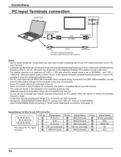
...maximum of the D-sub 15P Connector. • Change the "COMPONENT/RGB-IN SELECT" setting in the "SET UP" menu to "FULL". STANDBY G POWER ON INPUT MENU VOL + ENTER RGB PC cable AUDIO PC IN Mini D-sub 15p Audio Stereo plug Connect a cable which are DDC1/2B-compatible. Notes: • Due ... RGB signal connection). (see page 37) Signal Names for Mini D-sub 15P Connector 54 321 10 9 8 7 6 15 14 13 12 11 Pin Layout for PC Input Terminal Pin No. 1 2 3 4 5 Signal Name R (PR/CR) G (Y) B (PB/CB) NC (not connected) GND (Ground) Pin No. 6 7 8 9 10 Signal Name GND (Ground) GND (Ground) GND...
...maximum of the D-sub 15P Connector. • Change the "COMPONENT/RGB-IN SELECT" setting in the "SET UP" menu to "FULL". STANDBY G POWER ON INPUT MENU VOL + ENTER RGB PC cable AUDIO PC IN Mini D-sub 15p Audio Stereo plug Connect a cable which are DDC1/2B-compatible. Notes: • Due ... RGB signal connection). (see page 37) Signal Names for Mini D-sub 15P Connector 54 321 10 9 8 7 6 15 14 13 12 11 Pin Layout for PC Input Terminal Pin No. 1 2 3 4 5 Signal Name R (PR/CR) G (Y) B (PB/CB) NC (not connected) GND (Ground) Pin No. 6 7 8 9 10 Signal Name GND (Ground) GND (Ground) GND...

TH65PF9UK User Guide
Page 11
...SELF Control details Power ON Power OFF Volume 00 - 63 Audio MUTE OFF Audio MUTE ON Input select (toggle) Slot1 input Slot2 input Slot3 input PC input Screen mode select (toggle) NORMAL (4 : 3) ZOOM FULL JUST Panasonic AUTO With the power off, this unit will require software which allows the sending and receiving of...232C Straight cable SERIAL Pin layout for SERIAL Terminal D-sub 9p Notes: • Use the RS-232C cable to connect the computer to the Plasma Display. • The computer shown is for the first command to the RS-232C interface specification, so that order. The...
...SELF Control details Power ON Power OFF Volume 00 - 63 Audio MUTE OFF Audio MUTE ON Input select (toggle) Slot1 input Slot2 input Slot3 input PC input Screen mode select (toggle) NORMAL (4 : 3) ZOOM FULL JUST Panasonic AUTO With the power off, this unit will require software which allows the sending and receiving of...232C Straight cable SERIAL Pin layout for SERIAL Terminal D-sub 9p Notes: • Use the RS-232C cable to connect the computer to the Plasma Display. • The computer shown is for the first command to the RS-232C interface specification, so that order. The...

TH65PF9UK User Guide
Page 12
... 1 8 9 T.M.D.S. data 1/3 shielded 22 T.M.D.S. data 521 T.M.D.S. clock+ Notes: 12 T.M.D.S. Image deterioration may occur depending on the length or the quality of input signal source RR DVD Y, PB, PR, PB OUT Y Digital TV-SET-TOP-BOX (DTV-STB) L AUDIO OUT R RCA-BNC adapter plug Computer RGB ... COMPONENT/RGB IN SLOT3 Notes: • Change the "COMPONENT/RGB-IN SELECT" setting in the "SET UP" menu to page 45 for applicable input signal. • Use the DVI-D cable complying with the DVI standard. COMPONENT / RGB connection & RGB signal (R, G, B) COMPONENT VIDEO OUT ...
... 1 8 9 T.M.D.S. data 1/3 shielded 22 T.M.D.S. data 521 T.M.D.S. clock+ Notes: 12 T.M.D.S. Image deterioration may occur depending on the length or the quality of input signal source RR DVD Y, PB, PR, PB OUT Y Digital TV-SET-TOP-BOX (DTV-STB) L AUDIO OUT R RCA-BNC adapter plug Computer RGB ... COMPONENT/RGB IN SLOT3 Notes: • Change the "COMPONENT/RGB-IN SELECT" setting in the "SET UP" menu to page 45 for applicable input signal. • Use the DVI-D cable complying with the DVI standard. COMPONENT / RGB connection & RGB signal (R, G, B) COMPONENT VIDEO OUT ...
TH65PF9UK User Guide
Page 13
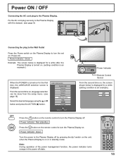
... condition is turned on . Power Indicator: Red (standby) Press the button on the remote control to turn the Plasma Display on for a while after the Plasma Display is turned on. (setting condition is an example.) When the POWER is an example). Power Indicator: Green Turn...Plasma Display off by pressing the when the Plasma Display is displayed. OSD LANGUAGE English (UK) Deutsch Français Italiano Español ENGLISH (US) SELECT SET INPUT MENU VOL + ENTER Power Indicator Remote Control Sensor From the second time on : Power-On. Fix the AC cord plug securely to the Plasma...
... condition is turned on . Power Indicator: Red (standby) Press the button on the remote control to turn the Plasma Display on for a while after the Plasma Display is turned on. (setting condition is an example.) When the POWER is an example). Power Indicator: Green Turn...Plasma Display off by pressing the when the Plasma Display is displayed. OSD LANGUAGE English (UK) Deutsch Français Italiano Español ENGLISH (US) SELECT SET INPUT MENU VOL + ENTER Power Indicator Remote Control Sensor From the second time on : Power-On. Fix the AC cord plug securely to the Plasma...

TH65PF9UK User Guide
Page 14
...Remote control sensor R - Indicator not illuminated (The unit will light. • Power-OFF .... Green • DPMS Orange (With PC input signal and during operation of surround sound are memorized separately for each time the SURROUND button is displayed: "+": press to move the cursor up...-ON ...... just as the power cord is pressed, the menu screen will switch. (see page 16) Normal Viewing PICTURE SETUP SOUND POS. /SIZE INPUT button (INPUT1, INPUT2, INPUT3 and PC selection) (see page 18) SURROUND button The surround setting switches on and off each AUDIO MENU (STANDARD, DYNAMIC...
...Remote control sensor R - Indicator not illuminated (The unit will light. • Power-OFF .... Green • DPMS Orange (With PC input signal and during operation of surround sound are memorized separately for each time the SURROUND button is displayed: "+": press to move the cursor up...-ON ...... just as the power cord is pressed, the menu screen will switch. (see page 16) Normal Viewing PICTURE SETUP SOUND POS. /SIZE INPUT button (INPUT1, INPUT2, INPUT3 and PC selection) (see page 18) SURROUND button The surround setting switches on and off each AUDIO MENU (STANDARD, DYNAMIC...

TH65PF9UK User Guide
Page 15
... ID lock (see page 36) Digital Zoom (see page 16, 17) DIRECT INPUT buttons Press the INPUT "1", "2", "3" or "PC" input mode selection button to select the INPUT mode. Note: After-image (image lag) may occur on the plasma display panel when a still picture is kept on at the power switch (see page... 13). POSITION buttons R button (see page 19) 3 Off timer The off timer indicator is 3 displayed only when the off timer has been set. PC NORMAL OFF TIMER 90 1 1 Input label 2 2 ...
... ID lock (see page 36) Digital Zoom (see page 16, 17) DIRECT INPUT buttons Press the INPUT "1", "2", "3" or "PC" input mode selection button to select the INPUT mode. Note: After-image (image lag) may occur on the plasma display panel when a still picture is kept on at the power switch (see page... 13). POSITION buttons R button (see page 19) 3 Off timer The off timer indicator is 3 displayed only when the off timer has been set. PC NORMAL OFF TIMER 90 1 1 Input label 2 2 ...

TH65PF9UK User Guide
Page 16
... 0 0 0 0 0 0 OFF 16 To SOUND adjust menu (see page 20) During "VIDEO (S VIDEO)", "Digital", "SDI" and "HDMI" input signal. To ADVANCED SETTINGS (see page 24) PICTURE 1/2 NORMALIZE NORMAL PICTURE MENU PICTURE BRIGHTNESS COLOR TINT SHARPNESS STANDARD 25 0 0 0 5 PICTURE 2/2 COLOR... TEMP COLOR MANAGEMENT ADVANCED SETTINGS NORMAL OFF ON Press to select "ON". Normal Viewing PICTURE SETUP SOUND POS. /SIZE [ from the unit ] - + INPUT MENU VOL ENTER 1 2 1 Press to select. 2 Press to enter ADVANCED SETTINGS. POS. /SIZE NORMALIZE NORMAL AUTO SETUP H-POS H-SIZE V-POS V-SIZE ...
... 0 0 0 0 0 0 OFF 16 To SOUND adjust menu (see page 20) During "VIDEO (S VIDEO)", "Digital", "SDI" and "HDMI" input signal. To ADVANCED SETTINGS (see page 24) PICTURE 1/2 NORMALIZE NORMAL PICTURE MENU PICTURE BRIGHTNESS COLOR TINT SHARPNESS STANDARD 25 0 0 0 5 PICTURE 2/2 COLOR... TEMP COLOR MANAGEMENT ADVANCED SETTINGS NORMAL OFF ON Press to select "ON". Normal Viewing PICTURE SETUP SOUND POS. /SIZE [ from the unit ] - + INPUT MENU VOL ENTER 1 2 1 Press to select. 2 Press to enter ADVANCED SETTINGS. POS. /SIZE NORMALIZE NORMAL AUTO SETUP H-POS H-SIZE V-POS V-SIZE ...
TH65PF9UK User Guide
Page 17
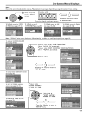
...RGB (see page 38, 39) SIGNAL [ RGB ] To SIGNAL screen for Digital (see page 38, 39) SIGNAL [ Digital ] 3D Y/C FILTER (NTSC) COLOR SYSTEM 3 : 2 PULLDOWN Panasonic AUTO (4 : 3) VIDEO NR ON AUTO OFF NORMAL OFF 3 : 2 PULLDOWN OFF VIDEO NR OFF SYNC 3 : 2 PULLDOWN VIDEO NR H-FREQ. 33.8 V-FREQ. 60.0 AUTO OFF .... 33.8 V-FREQ. 60.0 OFF OFF kHz Hz Note: "SIGNAL" setup menu displays a different setting condition for each adjust screen. [ from the unit ] - + INPUT MENU VOL ENTER Press the R button to return Press to return to "SET UP" menu. SET UP TIMER PRESENT TIME OF DAY 99:99 POWER...
...RGB (see page 38, 39) SIGNAL [ RGB ] To SIGNAL screen for Digital (see page 38, 39) SIGNAL [ Digital ] 3D Y/C FILTER (NTSC) COLOR SYSTEM 3 : 2 PULLDOWN Panasonic AUTO (4 : 3) VIDEO NR ON AUTO OFF NORMAL OFF 3 : 2 PULLDOWN OFF VIDEO NR OFF SYNC 3 : 2 PULLDOWN VIDEO NR H-FREQ. 33.8 V-FREQ. 60.0 AUTO OFF .... 33.8 V-FREQ. 60.0 OFF OFF kHz Hz Note: "SIGNAL" setup menu displays a different setting condition for each adjust screen. [ from the unit ] - + INPUT MENU VOL ENTER Press the R button to return Press to return to "SET UP" menu. SET UP TIMER PRESENT TIME OF DAY 99:99 POWER...

TH65PF9UK User Guide
Page 18
...which has been connected to select OSD LANGUAGE. Initial selections Selecting the input signal Select the input signals to be selected for the main picture and sub picture. Press to the Plasma Display. Press to select the input signal to be played back from the source connected to the component.../RGB input terminals. (see page 37) • In 2 screen display, the same input mode cannot be connected by installing the optional Terminal...
...which has been connected to select OSD LANGUAGE. Initial selections Selecting the input signal Select the input signals to be selected for the main picture and sub picture. Press to the Plasma Display. Press to select the input signal to be played back from the source connected to the component.../RGB input terminals. (see page 37) • In 2 screen display, the same input mode cannot be connected by installing the optional Terminal...

TH65PF9UK User Guide
Page 19
... in accordance with FULL mode, the adjustment is installed. Mode NORMAL 4 NORMAL Picture 3 Explanation NORMAL will depend on the Plasma Display Panel. 19 Notes: • For PC signal input, the mode switches between "NORMAL", "ZOOM" and "FULL" only. • For a 1125 (1080) / 60i ...is designed to automatically adjust the aspect ratio to a former adjustment. • Panasonic AUTO can not be displayed in Panasonic AUTO with the Panasonic AUTO mode setting (see page 38). Notes: • Panasonic AUTO mode is not possible. The size of the picture will display a ...
... in accordance with FULL mode, the adjustment is installed. Mode NORMAL 4 NORMAL Picture 3 Explanation NORMAL will depend on the Plasma Display Panel. 19 Notes: • For PC signal input, the mode switches between "NORMAL", "ZOOM" and "FULL" only. • For a 1125 (1080) / 60i ...is designed to automatically adjust the aspect ratio to a former adjustment. • Panasonic AUTO can not be displayed in Panasonic AUTO with the Panasonic AUTO mode setting (see page 38). Notes: • Panasonic AUTO mode is not possible. The size of the picture will display a ...
TH65PF9UK User Guide
Page 20
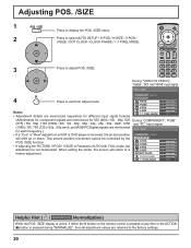
... the AUTO SETUP POS. /SIZE function. AUTO SETUP H-POS 0 H-SIZE 0 V-POS 0 Notes: • Adjustment details are memorized separately for different input signal formats V-SIZE 1:1 PIXEL MODE 0 OFF (Adjustments for component signals are memorized for each frequency.) • If a "Cue" or "Rew" ...signal from adjust mode. H-POS 0 H-SIZE 0 • If adjusting the PICTURE V-POS / V-SIZE in Panasonic AUTO with FULL mode, the V-POS 0 adjustment is received, the picture position NORMALIZE NORMAL will return to the factory settings. 20 POS. /SIZE NORMALIZE...
... the AUTO SETUP POS. /SIZE function. AUTO SETUP H-POS 0 H-SIZE 0 V-POS 0 Notes: • Adjustment details are memorized separately for different input signal formats V-SIZE 1:1 PIXEL MODE 0 OFF (Adjustments for component signals are memorized for each frequency.) • If a "Cue" or "Rew" ...signal from adjust mode. H-POS 0 H-SIZE 0 • If adjusting the PICTURE V-POS / V-SIZE in Panasonic AUTO with FULL mode, the V-POS 0 adjustment is received, the picture position NORMALIZE NORMAL will return to the factory settings. 20 POS. /SIZE NORMALIZE...

TH65PF9UK User Guide
Page 21
... figured out or shadowy, that the edge is pressed during "NORMALIZE", then all adjustment values are returned to replay 1920 × 1080 input signal. • Applicable input signal; 1125 / 50i · 60i · 24sF · 24p · 25p · 30p · 50p · 60p ·... OFF ON Notes: • Select ON when you would like to the factory settings. 21 DOT CLOCK (During "COMPONENT", "RGB" and "PC" input signal) Periodic striped pattern interference (noise) may occur when a striped pattern is minimized. Helpful Hint ( / NORMALIZE Normalization) While the POS. /SIZE ...
... figured out or shadowy, that the edge is pressed during "NORMALIZE", then all adjustment values are returned to replay 1920 × 1080 input signal. • Applicable input signal; 1125 / 50i · 60i · 24sF · 24p · 25p · 30p · 50p · 60p ·... OFF ON Notes: • Select ON when you would like to the factory settings. 21 DOT CLOCK (During "COMPONENT", "RGB" and "PC" input signal) Periodic striped pattern interference (noise) may occur when a striped pattern is minimized. Helpful Hint ( / NORMALIZE Normalization) While the POS. /SIZE ...

TH65PF9UK User Guide
Page 22
... - Normal Viewing [Picture and Picture] Main picture Sub picture [Picture out Picture] [Picture in picture. C VIDEO2 VIDEO1 A PC1 VIDEO2 Press to change input modes. Component - Component, Component - Notes: • The sub picture may not be possible to the small dimensions of the pictures. PC (RGB),...Picture] Main picture Sub picture Main picture Sub picture MULTI PIP A MULTI PIP B SWAP MULTI PIP AB SWAP A B SWAP Press to change input signal. Notes: • The sub picture sound is heard while a sub picture A PC1 VIDEO2 B SELECT A PC1 VIDEO2 B operation is ...
... - Normal Viewing [Picture and Picture] Main picture Sub picture [Picture out Picture] [Picture in picture. C VIDEO2 VIDEO1 A PC1 VIDEO2 Press to change input modes. Component - Component, Component - Notes: • The sub picture may not be possible to the small dimensions of the pictures. PC (RGB),...Picture] Main picture Sub picture Main picture Sub picture MULTI PIP A MULTI PIP B SWAP MULTI PIP AB SWAP A B SWAP Press to change input signal. Notes: • The sub picture sound is heard while a sub picture A PC1 VIDEO2 B SELECT A PC1 VIDEO2 B operation is ...

TH65PF9UK User Guide
Page 23
...". 3 Press and hold until the Options menu is selected in Audio OUT (PIP) (See page 26). • In 2 screen display, the same input mode cannot be displayed as above. INPUT lock Off Studio W/B Off Advanced PIP Off Display size Off Press to adjust the menu. Options 1/3 Off-timer function Enable Onscreen display...
...". 3 Press and hold until the Options menu is selected in Audio OUT (PIP) (See page 26). • In 2 screen display, the same input mode cannot be displayed as above. INPUT lock Off Studio W/B Off Advanced PIP Off Display size Off Press to adjust the menu. Options 1/3 Off-timer function Enable Onscreen display...

TH65PF9UK User Guide
Page 24
...Displays velvety picture. Helpful Hint ( / NORMALIZE Normalization) While the "PICTURE" menu is displayed, if either the N button on signal, input and menu setting. PICTURE Adjustments 1 Press to display the PICTURE menu. 2 Select to adjust. Press to select the menu to adjust... each item. ADVANCED SETTINGS ON Enables fine picture adjustment at any time or the ACTION ( ) button is grayout. ADVANCED SETTINGS NORMALIZE NORMAL BLACK EXTENSION INPUT LEVEL W/B HIGH R W/B HIGH B W/B LOW R W/B LOW B GAMMA AGC 0 0 0 0 0 0 2.2 OFF ADVANCED SETTINGS OFF Displays images ...
...Displays velvety picture. Helpful Hint ( / NORMALIZE Normalization) While the "PICTURE" menu is displayed, if either the N button on signal, input and menu setting. PICTURE Adjustments 1 Press to display the PICTURE menu. 2 Select to adjust. Press to select the menu to adjust... each item. ADVANCED SETTINGS ON Enables fine picture adjustment at any time or the ACTION ( ) button is grayout. ADVANCED SETTINGS NORMALIZE NORMAL BLACK EXTENSION INPUT LEVEL W/B HIGH R W/B HIGH B W/B LOW R W/B LOW B GAMMA AGC 0 0 0 0 0 0 2.2 OFF ADVANCED SETTINGS OFF Displays images ...

TH65PF9UK User Guide
Page 25
... the white balance for dark red areas. Steps 1 and 2 affect each other's settings, so repeat each input terminal. • The adjustment range values should be adjusted when the input signal is increased with a bright picture or reduced with a dark picture. ADVANCED SETTINGS Item BLACK EXTENSION..." menu is displayed, if either the N button is pressed at any time or the ACTION ( ) button is pressed during "VIDEO (S VIDEO)" input signal. • In PICTURE, there is not a noticeable change the level of each function (PICTURE, BRIGHTNESS, COLOR, TINT, SHARPNESS) for each PICTURE...
... the white balance for dark red areas. Steps 1 and 2 affect each other's settings, so repeat each input terminal. • The adjustment range values should be adjusted when the input signal is increased with a bright picture or reduced with a dark picture. ADVANCED SETTINGS Item BLACK EXTENSION..." menu is displayed, if either the N button is pressed at any time or the ACTION ( ) button is pressed during "VIDEO (S VIDEO)" input signal. • In PICTURE, there is not a noticeable change the level of each function (PICTURE, BRIGHTNESS, COLOR, TINT, SHARPNESS) for each PICTURE...

TH65PF9UK User Guide
Page 27
.... This is shown in operation, "Adjusting POS. /SIZE" cannot be selected while in the following buttons can be operated. [Remote control] [Unit] POSITION / ACTION button - + INPUT MENU VOL ENTER VOL button MUTE button VOL button SURROUND button OFF TIMER button 2 Select the area of the displayed image. 1 Display the "Operation Guide...
.... This is shown in operation, "Adjusting POS. /SIZE" cannot be selected while in the following buttons can be operated. [Remote control] [Unit] POSITION / ACTION button - + INPUT MENU VOL ENTER VOL button MUTE button VOL button SURROUND button OFF TIMER button 2 Select the area of the displayed image. 1 Display the "Operation Guide...
TH65PF9UK User Guide
Page 28
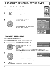
... DAY 99:99 SET PRESENT TIME OF DAY 99:99 Press to select Set. PRESENT TIME SETUP / SET UP TIMER The timer can switch the Plasma Display ON or OFF. button: Forward SET PRESENT TIME OF DAY 99:99 button: Back Notes: • Pressing " " or " " button once changes PRESENT TIME ... " " or " " button continuously changes PRESENT TIME OF DAY by 15 minutes. 2 Press to store PRESENT TIME SETUP. SET UP 1/2 SIGNAL COMPONENT/RGB-IN SELECT RGB INPUT LABEL PC POWER SAVE OFF STANDBY SAVE OFF Press to select SET UP TIMER or PRESENT TIME SETUP. To set up PRESENT TIME OF DAY...
... DAY 99:99 SET PRESENT TIME OF DAY 99:99 Press to select Set. PRESENT TIME SETUP / SET UP TIMER The timer can switch the Plasma Display ON or OFF. button: Forward SET PRESENT TIME OF DAY 99:99 button: Back Notes: • Pressing " " or " " button once changes PRESENT TIME ... " " or " " button continuously changes PRESENT TIME OF DAY by 15 minutes. 2 Press to store PRESENT TIME SETUP. SET UP 1/2 SIGNAL COMPONENT/RGB-IN SELECT RGB INPUT LABEL PC POWER SAVE OFF STANDBY SAVE OFF Press to select SET UP TIMER or PRESENT TIME SETUP. To set up PRESENT TIME OF DAY...


