
TH65PF9UK User Guide
Page 4
... Supplied 8 Remote Control Batteries 8 Connections 9 PC Input Terminals connection 10 SERIAL Terminals connection 11 DVI-D connection 12 COMPONENT / RGB connection & RGB signal (R, G, B 12 Power ON / OFF 13 Basic Controls 14 On-Screen Menu Displays 16 Initial selections 18 Selecting the input signal 18 Selecting the On-Screen Menu Language 18 ASPECT Controls 19 Adjusting POS. /SIZE 20 MULTI PIP 22 Advanced PIP 23 PICTURE Adjustments 24 ADVANCED SETTINGS 25 SOUND Adjustment 26 MUTE 26 Digital Zoom 27 PRESENT TIME SETUP / SET UP TIMER 28 PRESENT TIME SETUP 28 SET...
... Supplied 8 Remote Control Batteries 8 Connections 9 PC Input Terminals connection 10 SERIAL Terminals connection 11 DVI-D connection 12 COMPONENT / RGB connection & RGB signal (R, G, B 12 Power ON / OFF 13 Basic Controls 14 On-Screen Menu Displays 16 Initial selections 18 Selecting the input signal 18 Selecting the On-Screen Menu Language 18 ASPECT Controls 19 Adjusting POS. /SIZE 20 MULTI PIP 22 Advanced PIP 23 PICTURE Adjustments 24 ADVANCED SETTINGS 25 SOUND Adjustment 26 MUTE 26 Digital Zoom 27 PRESENT TIME SETUP / SET UP TIMER 28 PRESENT TIME SETUP 28 SET...
TH65PF9UK User Guide
Page 5
... receiving antenna. • Increase the separation between the equipment and receiver. • Connect the equipment into an outlet on the Plasma Display. Operation is no special notation has been made of still pictures include logos, video games, computer images, teletext and images displayed in a residential installation. However, there is subject to operate this device must accept any changes or modifications to this monitor...
... receiving antenna. • Increase the separation between the equipment and receiver. • Connect the equipment into an outlet on the Plasma Display. Operation is no special notation has been made of still pictures include logos, video games, computer images, teletext and images displayed in a residential installation. However, there is subject to operate this device must accept any changes or modifications to this monitor...

TH65PF9UK User Guide
Page 6
... objects close . This Plasma Display radiates infrared rays, therefore it with by Matsushita Electric Industrial Co., Ltd.) • Speakers TY-SP65P7W-K • Pedestal TY-ST65-K • Wall-hanging bracket (vertical TY-WK65PV7 • Wall-hanging bracket (angled TY-WK65PR8 • BNC Component Video Terminal Board TY-42TM6A • BNC Composite Video Terminal Board TY-42TM6B • BNC Dual Video Terminal Board TY-FB9BD • DVI-D Terminal Board for use...
... objects close . This Plasma Display radiates infrared rays, therefore it with by Matsushita Electric Industrial Co., Ltd.) • Speakers TY-SP65P7W-K • Pedestal TY-ST65-K • Wall-hanging bracket (vertical TY-WK65PV7 • Wall-hanging bracket (angled TY-WK65PR8 • BNC Component Video Terminal Board TY-42TM6A • BNC Composite Video Terminal Board TY-42TM6B • BNC Dual Video Terminal Board TY-FB9BD • DVI-D Terminal Board for use...

TH65PF9UK User Guide
Page 7
... be made from the Plasma Display, unplug the power cord immediately. • Continuous use If a problem occurs (such as insect sprays, solvents and thinner, otherwise the quality of the Plasma Display. Securely insert the power cord plug as far as insect sprays, solvents and thinner, otherwise the quality of the panel with volatile substances such as no picture or no sound), or if smoke...
... be made from the Plasma Display, unplug the power cord immediately. • Continuous use If a problem occurs (such as insect sprays, solvents and thinner, otherwise the quality of the Plasma Display. Securely insert the power cord plug as far as insect sprays, solvents and thinner, otherwise the quality of the panel with volatile substances such as no picture or no sound), or if smoke...
TH65PF9UK User Guide
Page 9
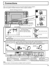
... secure cables connected to the Plasma Display. 2 Fix the left side clamper. 3 Fix the right side clamper. Keep the knob pressed. - Note: The power plug in the illustration may not be sure to the speaker's Installation Manual for details on speaker installation. While ensuring there is sufficient slack in the figure. Close Open 2 Push until the hook clicks. 2. Refer to use only the...
... secure cables connected to the Plasma Display. 2 Fix the left side clamper. 3 Fix the right side clamper. Keep the knob pressed. - Note: The power plug in the illustration may not be sure to the speaker's Installation Manual for details on speaker installation. While ensuring there is sufficient slack in the figure. Close Open 2 Push until the hook clicks. 2. Refer to use only the...
TH65PF9UK User Guide
Page 10
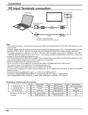
... be displayed properly if the signals exceed 1,200 lines.) • The display resolution is a maximum of the D-sub 15P Connector. • Change the "COMPONENT/RGB-IN SELECT" setting in the illustration is set the horizontal and vertical scanning frequencies for PC signals which matches the audio output terminal on the computer. STANDBY G POWER ON INPUT MENU VOL + ENTER RGB PC cable AUDIO PC IN Mini D-sub 15p Audio Stereo plug Connect a cable which...
... be displayed properly if the signals exceed 1,200 lines.) • The display resolution is a maximum of the D-sub 15P Connector. • Change the "COMPONENT/RGB-IN SELECT" setting in the illustration is set the horizontal and vertical scanning frequencies for PC signals which matches the audio output terminal on the computer. STANDBY G POWER ON INPUT MENU VOL + ENTER RGB PC cable AUDIO PC IN Mini D-sub 15p Audio Stereo plug Connect a cable which...

TH65PF9UK User Guide
Page 12
... of input signal source RR DVD Y, PB, PR, PB OUT Y Digital TV-SET-TOP-BOX (DTV-STB) L AUDIO OUT R RCA-BNC adapter plug Computer RGB Camcorder or R AUDIO L PR/CR/R PB/CB/B Y/G COMPONENT/RGB IN SLOT3 Notes: • Change the "COMPONENT/RGB-IN SELECT" setting in the "SET UP" menu to page 45 for applicable input signal. • Use the DVI-D cable complying with DVI-D video out DVI-D video cable (Within 5 m) AUDIO DVI-D IN SLOT2 Mini-plug (M3) DVI-D Input...
... of input signal source RR DVD Y, PB, PR, PB OUT Y Digital TV-SET-TOP-BOX (DTV-STB) L AUDIO OUT R RCA-BNC adapter plug Computer RGB Camcorder or R AUDIO L PR/CR/R PB/CB/B Y/G COMPONENT/RGB IN SLOT3 Notes: • Change the "COMPONENT/RGB-IN SELECT" setting in the "SET UP" menu to page 45 for applicable input signal. • Use the DVI-D cable complying with DVI-D video out DVI-D video cable (Within 5 m) AUDIO DVI-D IN SLOT2 Mini-plug (M3) DVI-D Input...
TH65PF9UK User Guide
Page 13
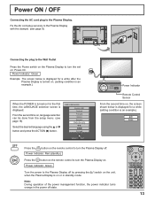
...) SELECT SET INPUT MENU VOL + ENTER Power Indicator Remote Control Sensor From the second time on . Power ON / OFF Connecting the AC cord plug to the Plasma Display with the clamper. (see page 18) Select the desired language using the or button and press the ACTION ( ) button. Power Indicator: Red (standby) Press the button on the remote control to the Plasma Display off . Fix the AC cord plug securely to the Plasma Display. PC FULL Press the button on : Power-On.
...) SELECT SET INPUT MENU VOL + ENTER Power Indicator Remote Control Sensor From the second time on . Power ON / OFF Connecting the AC cord plug to the Plasma Display with the clamper. (see page 18) Select the desired language using the or button and press the ACTION ( ) button. Power Indicator: Red (standby) Press the button on the remote control to the Plasma Display off . Fix the AC cord plug securely to the Plasma Display. PC FULL Press the button on : Power-On.

TH65PF9UK User Guide
Page 14
... menu screen is displayed: "+": press to move the cursor down (see page 16) Power Indicator The Power Indicator will light. • Power-OFF .... Green • DPMS Orange (With PC input signal and during operation of surround sound are memorized separately for each time the SURROUND button is still inserted into the wall outlet.) • Standby.......... Indicator not illuminated (The unit will switch. (see page 16) Normal Viewing PICTURE SETUP SOUND...
... menu screen is displayed: "+": press to move the cursor down (see page 16) Power Indicator The Power Indicator will light. • Power-OFF .... Green • DPMS Orange (With PC input signal and during operation of surround sound are memorized separately for each time the SURROUND button is still inserted into the wall outlet.) • Standby.......... Indicator not illuminated (The unit will switch. (see page 16) Normal Viewing PICTURE SETUP SOUND...

TH65PF9UK User Guide
Page 15
... displayed image. 15 OFF TIMER button The Plasma Display can only display the slot which is not installed, it automatically displays the current input signal. SET UP button (see page 27) Press to stand-by after -image. Remote ID lock (see page 36) Digital Zoom (see page 16, 17) DIRECT INPUT buttons Press the INPUT "1", "2", "3" or "PC" input mode selection button to Standby mode. Press ON to INPUT mode. Press OFF to turn the Plasma Display On, from Standby mode. PC NORMAL OFF TIMER...
... displayed image. 15 OFF TIMER button The Plasma Display can only display the slot which is not installed, it automatically displays the current input signal. SET UP button (see page 27) Press to stand-by after -image. Remote ID lock (see page 36) Digital Zoom (see page 16, 17) DIRECT INPUT buttons Press the INPUT "1", "2", "3" or "PC" input mode selection button to Standby mode. Press ON to INPUT mode. Press OFF to turn the Plasma Display On, from Standby mode. PC NORMAL OFF TIMER...
TH65PF9UK User Guide
Page 17
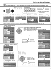
... the R button to return to next menu screen. On-Screen Menu Displays Note: Menu that cannot be adjusted is selected). POWER ON FUNCTION OFF POWER ON TIME 0:00 POWER OFF FUNCTION OFF POWER OFF TIME 0:00 17 Adjustable menu changes depending on signal, input and menu setting. 2 Press to access each input signal. (see page 18) To setup SCREENSAVER (See page 30-32) SCREENSAVER PRESENT TIME OF DAY 99:99 START FUNCTION WHITE BAR SCROLL MODE TIME OF...
... the R button to return to next menu screen. On-Screen Menu Displays Note: Menu that cannot be adjusted is selected). POWER ON FUNCTION OFF POWER ON TIME 0:00 POWER OFF FUNCTION OFF POWER OFF TIME 0:00 17 Adjustable menu changes depending on signal, input and menu setting. 2 Press to access each input signal. (see page 18) To setup SCREENSAVER (See page 30-32) SCREENSAVER PRESENT TIME OF DAY 99:99 START FUNCTION WHITE BAR SCROLL MODE TIME OF...

TH65PF9UK User Guide
Page 18
... for the main picture and sub picture. Input signals will change as follows: INPUT1 INPUT2 INPUT3 PC Notes: • Selecting is not installed into the SLOT. • Select to match the signals from the equipment which has been connected to the component/RGB input terminals. (see page 37) • In 2 screen display, the same input mode cannot be played back from the source connected to the Plasma Display.
... for the main picture and sub picture. Input signals will change as follows: INPUT1 INPUT2 INPUT3 PC Notes: • Selecting is not installed into the SLOT. • Select to match the signals from the equipment which has been connected to the component/RGB input terminals. (see page 37) • In 2 screen display, the same input mode cannot be played back from the source connected to the Plasma Display.

TH65PF9UK User Guide
Page 19
... on the original signal. 4 3 For an elongated image Panasonic 4 AUTO 3 For a 4:3 image 16 Panasonic AUTO 9 Image is expanded Changes in Picture : NORMAL FULL • Others : Aspect switching is not possible. ZOOM 4 3 16 ZOOM ZOOM mode magnifies the central section of the screen so that the ASPECT be selected only during Video signal input. • The aspect mode is installed. The display will display a 4:3 picture at its maximum size but with...
... on the original signal. 4 3 For an elongated image Panasonic 4 AUTO 3 For a 4:3 image 16 Panasonic AUTO 9 Image is expanded Changes in Picture : NORMAL FULL • Others : Aspect switching is not possible. ZOOM 4 3 16 ZOOM ZOOM mode magnifies the central section of the screen so that the ASPECT be selected only during Video signal input. • The aspect mode is installed. The display will display a 4:3 picture at its maximum size but with...
TH65PF9UK User Guide
Page 20
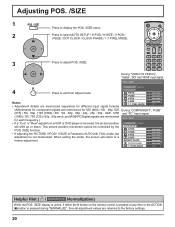
...adjust POS. /SIZE. This picture position movement cannot be controlled by the AUTO SETUP POS. /SIZE function. Adjusting POS. /SIZE 1 Press to display the POS. /SIZE menu. 2 Press to select AUTO SETUP / H-POS / H-SIZE / V-POS / V-SIZE / DOT CLOCK / CLOCK PHASE / 1:1 PIXEL MODE. 3 Press to exit from a VCR or DVD player is not memorized. During "VIDEO (S VIDEO)", "Digital", "SDI" and "HDMI" input signal. AUTO SETUP H-POS 0 H-SIZE 0 V-POS 0 Notes: • Adjustment details are memorized separately for different input signal formats V-SIZE 1:1 PIXEL MODE 0 OFF (Adjustments...
...adjust POS. /SIZE. This picture position movement cannot be controlled by the AUTO SETUP POS. /SIZE function. Adjusting POS. /SIZE 1 Press to display the POS. /SIZE menu. 2 Press to select AUTO SETUP / H-POS / H-SIZE / V-POS / V-SIZE / DOT CLOCK / CLOCK PHASE / 1:1 PIXEL MODE. 3 Press to exit from a VCR or DVD player is not memorized. During "VIDEO (S VIDEO)", "Digital", "SDI" and "HDMI" input signal. AUTO SETUP H-POS 0 H-SIZE 0 V-POS 0 Notes: • Adjustment details are memorized separately for different input signal formats V-SIZE 1:1 PIXEL MODE 0 OFF (Adjustments...

TH65PF9UK User Guide
Page 21
... MODE Adjusts the display size when 1125i, 1125p or 1250i signal is displayed. AUTO SETUP H-POS Adjusting POS. /SIZE Automatically adjust H-POS / V-POS / CLOCK PHASE / DOT CLOCK and set H-SIZE / V-SIZE the standard value when RGB signal is selected. In such case, press AUTO SETUP again after changing the image to the clearer one. • When DVI-D is shown around the image. • H-SIZE, V-SIZE and DOT CLOCK cannot be made . V-POS Adjust the vertical...
... MODE Adjusts the display size when 1125i, 1125p or 1250i signal is displayed. AUTO SETUP H-POS Adjusting POS. /SIZE Automatically adjust H-POS / V-POS / CLOCK PHASE / DOT CLOCK and set H-SIZE / V-SIZE the standard value when RGB signal is selected. In such case, press AUTO SETUP again after changing the image to the clearer one. • When DVI-D is shown around the image. • H-SIZE, V-SIZE and DOT CLOCK cannot be made . V-POS Adjust the vertical...

TH65PF9UK User Guide
Page 37
... AV images Select "SIGNAL" from adjust mode. COMPONENT RGB 3 Press to exit from the "SET UP" menu during VIDEO (S VIDEO) input signal mode. ("SIGNAL [VIDEO]" menu is installed. RGB INPUT LABEL PC POWER SAVE OFF STANDBY SAVE OFF POWER MANAGEMENT OFF AUTO POWER OFF OSD LANGUAGE OFF ENGLISH (US) 2 Press ACTION ( ) button Press to exit from the source connected to the COMPONENT / RGB input terminals. SIGNAL [ VIDEO ] Note: When ON, this setting only affects NTSC input signals. 3D Y/C FILTER (NTSC) COLOR...
... AV images Select "SIGNAL" from adjust mode. COMPONENT RGB 3 Press to exit from the "SET UP" menu during VIDEO (S VIDEO) input signal mode. ("SIGNAL [VIDEO]" menu is installed. RGB INPUT LABEL PC POWER SAVE OFF STANDBY SAVE OFF POWER MANAGEMENT OFF AUTO POWER OFF OSD LANGUAGE OFF ENGLISH (US) 2 Press ACTION ( ) button Press to exit from the source connected to the COMPONENT / RGB input terminals. SIGNAL [ VIDEO ] Note: When ON, this setting only affects NTSC input signals. 3D Y/C FILTER (NTSC) COLOR...

TH65PF9UK User Guide
Page 42
... the "Button lock", "Remocon User level" or "Remote ID" adjustments, set Display vertically. MENU & ENTER: Locks and buttons on the remote control and hold for the upward direction when you set all the values "Off" so that all of an external command can use normal remote control operations. You can be used in "Remote ID" or "Serial ID". Sets the panel ID Control. Auto: Power is transmitted to the slot power only when main power is turned on the remote control.
... the "Button lock", "Remocon User level" or "Remote ID" adjustments, set Display vertically. MENU & ENTER: Locks and buttons on the remote control and hold for the upward direction when you set all the values "Off" so that all of an external command can use normal remote control operations. You can be used in "Remote ID" or "Serial ID". Sets the panel ID Control. Auto: Power is transmitted to the slot power only when main power is turned on the remote control.

TH65PF9UK User Guide
Page 44
... Fluorescent light Volume (Check whether the mute function has been activated on the remote control.) Not plugged into AC outlet Not switched on PICTURE and BRIGHTNESS/Volume setting (Check by pressing the power switch or stand-by any other aspects. may change depending on , a sound of program shown: This is cut off when I use the zoom function. When the power is turned on the kind of the display panel being used...
... Fluorescent light Volume (Check whether the mute function has been activated on the remote control.) Not plugged into AC outlet Not switched on PICTURE and BRIGHTNESS/Volume setting (Check by pressing the power switch or stand-by any other aspects. may change depending on , a sound of program shown: This is cut off when I use the zoom function. When the power is turned on the kind of the display panel being used...
TH65PF9UK User Guide
Page 46
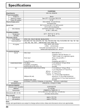
...(use HD port) with/picture 1.0 Vp-p (high impedance) without/picture 0.3 Vp-p (high impedance) AUDIO IN (M3 JACK) 0.5 Vrms SERIAL SPEAKERS (8 :) EXTERNAL CONTROL TERMINAL (D-SUB 9PIN) RS-232C COMPATIBLE 20 W [10 W + 10 W] (10 % THD) Accessories Supplied Remote Control Transmitter Batteries Fixing bands Dimensions (W × H × D) EUR7636070R 2 × AA Size (TMME203 or TMME187) × 2 61.2" (1,554 mm) × 36.4" (925 mm) × 3.9" (99 mm) (excluding handle portion) Mass (weight...
...(use HD port) with/picture 1.0 Vp-p (high impedance) without/picture 0.3 Vp-p (high impedance) AUDIO IN (M3 JACK) 0.5 Vrms SERIAL SPEAKERS (8 :) EXTERNAL CONTROL TERMINAL (D-SUB 9PIN) RS-232C COMPATIBLE 20 W [10 W + 10 W] (10 % THD) Accessories Supplied Remote Control Transmitter Batteries Fixing bands Dimensions (W × H × D) EUR7636070R 2 × AA Size (TMME203 or TMME187) × 2 61.2" (1,554 mm) × 36.4" (925 mm) × 3.9" (99 mm) (excluding handle portion) Mass (weight...
TH65PF9UK User Guide
Page 48
... days-Replacement only (content not covered) P2 Cards (Content not covered) Video Heads 1 year or 2,000 hrs. (prorated) Whichever comes first D5 Video heads 1 year or 500 hrs. Whichever comes first Plasma Displays 1 year (burn-in not covered) Hard Drive Disk Unit 1 year plus your purchase receipt, as PCI) warrants this warranty. No liability is a condition of warranty service. Panasonic Broadcast & Television...
... days-Replacement only (content not covered) P2 Cards (Content not covered) Video Heads 1 year or 2,000 hrs. (prorated) Whichever comes first D5 Video heads 1 year or 500 hrs. Whichever comes first Plasma Displays 1 year (burn-in not covered) Hard Drive Disk Unit 1 year plus your purchase receipt, as PCI) warrants this warranty. No liability is a condition of warranty service. Panasonic Broadcast & Television...


