

TH50PHD3U User Guide
Page 5
... Instructions 3 ASPECT Controls 22 FCC STATEMENT 6 Adjusting PICTURE POS./SIZE 24 Safety Precautions 7 SOUND Adjustment 26 Accessories 9 MUTE 26 Accessories Supplied 9 SURROUND Controls 27 Optional Accessories 9 PICTURE Adjustments 28 Remote Control Batteries 10 ADVANCED SETTINGS 29 Basic Controls 11 SET UP for Input Signals 30 Connections 12 COMPONENT/RGB IN SELECT 30 How to connect the speakers 13 Adjusting unnatural video images How to connect the AV Input Terminals 13 (3D Y/C FILTER 30 How to connect the TUNER Input...
... Instructions 3 ASPECT Controls 22 FCC STATEMENT 6 Adjusting PICTURE POS./SIZE 24 Safety Precautions 7 SOUND Adjustment 26 Accessories 9 MUTE 26 Accessories Supplied 9 SURROUND Controls 27 Optional Accessories 9 PICTURE Adjustments 28 Remote Control Batteries 10 ADVANCED SETTINGS 29 Basic Controls 11 SET UP for Input Signals 30 Connections 12 COMPONENT/RGB IN SELECT 30 How to connect the speakers 13 Adjusting unnatural video images How to connect the AV Input Terminals 13 (3D Y/C FILTER 30 How to connect the TUNER Input...
TH50PHD3U User Guide
Page 7
... a problem occurs (such as it repaired at an Authorized Service Center. If using some other setting-up Do not place the High Definition Plasma Display on sloped or unstable surfaces. • The High Definition Plasma Display may occur which could result in use of the Display under these conditions might damage the power cable. Securely insert the power cord plug as far as no picture or no sound...
... a problem occurs (such as it repaired at an Authorized Service Center. If using some other setting-up Do not place the High Definition Plasma Display on sloped or unstable surfaces. • The High Definition Plasma Display may occur which could result in use of the Display under these conditions might damage the power cable. Securely insert the power cord plug as far as no picture or no sound...
TH50PHD3U User Guide
Page 8
... the cables which might damage the insulation and cause fire. Safety Precautions CAUTION This High Definition Plasma Display is for use only with any other hard objects. Use with the following accessories are manufactured by Matsushita Electric Industrial Co., Ltd.) • Speakers TY-SP50PHD3W • Pedestal TY-ST42PT1U • Wall stand TY-ST42PW1 • Mobile stand TY-ST42PF3 • Wall-hanging bracket (vertical...
... the cables which might damage the insulation and cause fire. Safety Precautions CAUTION This High Definition Plasma Display is for use only with any other hard objects. Use with the following accessories are manufactured by Matsushita Electric Industrial Co., Ltd.) • Speakers TY-SP50PHD3W • Pedestal TY-ST42PT1U • Wall stand TY-ST42PW1 • Mobile stand TY-ST42PF3 • Wall-hanging bracket (vertical...
TH50PHD3U User Guide
Page 11
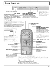
... Controls R - Green Input button (VIDEO (S-VIDEO)/COMPONENT, RGB/PC Mode Selection) Push the "INPUT" button to increase or decrease the sound volume level. The High Definition Plasma Display may be preset to switch to display the current system status. Status button Push the "Status" button to stand-by (ON/OFF) button The High Definition Plasma Display must first be plugged into the wall outlet.) • Stand-by .... Indicator not illuminated (The unit will light. • Power...
... Controls R - Green Input button (VIDEO (S-VIDEO)/COMPONENT, RGB/PC Mode Selection) Push the "INPUT" button to increase or decrease the sound volume level. The High Definition Plasma Display may be preset to switch to display the current system status. Status button Push the "Status" button to stand-by (ON/OFF) button The High Definition Plasma Display must first be plugged into the wall outlet.) • Stand-by .... Indicator not illuminated (The unit will light. • Power...
TH50PHD3U User Guide
Page 13
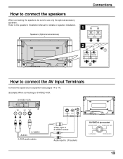
... S-VIDEO 4 pin socket Luminance earth Chrominance earth Luminance in Chrominance in 13 Refer to the speaker's Installation Manual for details on speaker installation. 1 Speakers (Optional accessories) Connections 2 1 2 How to connect the AV Input Terminals Connect the signal source equipment (see pages 14 to 17). (Example) When connecting an S-VIDEO VCR (S-VIDEO VCR) Audio OUT R L Video OUT S-Video OUT AUDIO S-VIDEO 2×RCA audio cables L S-VIDEO VIDEO AV IN AUDIO R Video input to S-VIDEO socket Audio input to use only the optional accessory speakers.
... S-VIDEO 4 pin socket Luminance earth Chrominance earth Luminance in Chrominance in 13 Refer to the speaker's Installation Manual for details on speaker installation. 1 Speakers (Optional accessories) Connections 2 1 2 How to connect the AV Input Terminals Connect the signal source equipment (see pages 14 to 17). (Example) When connecting an S-VIDEO VCR (S-VIDEO VCR) Audio OUT R L Video OUT S-Video OUT AUDIO S-VIDEO 2×RCA audio cables L S-VIDEO VIDEO AV IN AUDIO R Video input to S-VIDEO socket Audio input to use only the optional accessory speakers.

TH50PHD3U User Guide
Page 14
... socket AUDIO R RCA-BNC adapter plug Audio input to L/R sockets How to the High Definition Plasma Display and CONTROLLER/TUNER is reserved for use with future external compatible components. CONTROLLER/TUNER L AUDIO R AUDIO PC IN TUNER IN Notes: (1) Additional equipment and cables shown are not supplied with this set. (2) When connecting video cables, priority is given to the S-VIDEO cable when the S-VIDEO input terminal and the video input terminal are connected at the same time. (3) Install the CONTROLLER/TUNER at least 15.75 inch...
... socket AUDIO R RCA-BNC adapter plug Audio input to L/R sockets How to the High Definition Plasma Display and CONTROLLER/TUNER is reserved for use with future external compatible components. CONTROLLER/TUNER L AUDIO R AUDIO PC IN TUNER IN Notes: (1) Additional equipment and cables shown are not supplied with this set. (2) When connecting video cables, priority is given to the S-VIDEO cable when the S-VIDEO input terminal and the video input terminal are connected at the same time. (3) Install the CONTROLLER/TUNER at least 15.75 inch...

TH50PHD3U User Guide
Page 15
... equipment and cables shown are not supplied with this set . Connections How to connect the COMPONENT/RGB Input Terminals Component signals (Y, PB, PR) connection DVD Player L Audio R OUT L DVD (Y,PB, PR) OUT Y PB PR VD RCA-BNC adapter plug HD PR/CR/R PB/CB/B Y/G COMPONENT/RGB IN AUDIO R Y, PB, PR 3×RCA video cables AUDIO 2×RCA audio cables Audio input to L/R sockets Notes: (1) Change the "COMPONENT/RGB-IN" setting in the "SET UP" menu to...
... equipment and cables shown are not supplied with this set . Connections How to connect the COMPONENT/RGB Input Terminals Component signals (Y, PB, PR) connection DVD Player L Audio R OUT L DVD (Y,PB, PR) OUT Y PB PR VD RCA-BNC adapter plug HD PR/CR/R PB/CB/B Y/G COMPONENT/RGB IN AUDIO R Y, PB, PR 3×RCA video cables AUDIO 2×RCA audio cables Audio input to L/R sockets Notes: (1) Change the "COMPONENT/RGB-IN" setting in the "SET UP" menu to...
TH50PHD3U User Guide
Page 16
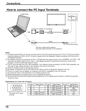
... lines will need to connect the PC Input Terminals COMPUTER AUDIO PC IN POWER / R - STANDBY G POWER ON INPUT - If the computer being connected is not DDC1/2B-compatible, you will not be displayed properly.) (2) The display resolution is a maximum of connection. (4) Some PC models cannot be connected to the set. (5) An adapter is no need to make setting changes to the computer at the time of 1024 × 768 dots when the aspect mode...
... lines will need to connect the PC Input Terminals COMPUTER AUDIO PC IN POWER / R - STANDBY G POWER ON INPUT - If the computer being connected is not DDC1/2B-compatible, you will not be displayed properly.) (2) The display resolution is a maximum of connection. (4) Some PC models cannot be connected to the set. (5) An adapter is no need to make setting changes to the computer at the time of 1024 × 768 dots when the aspect mode...

TH50PHD3U User Guide
Page 17
... signal does POF not need to this unit) PC mode Screen mode select (toggle) NORMAL (4:3) ZOOM FULL JUST Panasonic AUTO 17 DAM Parameter None None None None None None VID YP1 RG1 None NORM ZOOM FULL JUST SELF Control details Power ON Power OFF Volume increase Volume decrease Mute (toggle) Input select (toggle) AV Mode Component / RGB mode (processed as a Y/PB/PR or RGB signals as a programming...
... signal does POF not need to this unit) PC mode Screen mode select (toggle) NORMAL (4:3) ZOOM FULL JUST Panasonic AUTO 17 DAM Parameter None None None None None None VID YP1 RG1 None NORM ZOOM FULL JUST SELF Control details Power ON Power OFF Volume increase Volume decrease Mute (toggle) Input select (toggle) AV Mode Component / RGB mode (processed as a Y/PB/PR or RGB signals as a programming...

TH50PHD3U User Guide
Page 18
... Definition Plasma Display off Power Indicator: Red (standby) Press the button on the remote control to the Wall Outlet R - STANDBY G POWER ON INPUT - STANDBY G POWER ON TH-50PHD3 Power Indicator Push the POWER switch on the High Definition Plasma Display to turn the power for a while (setting condition is displayed. VOL + R - From the second time on or in standby mode. VIDEO NORMAL INPUT SURROUND VOL N R 18 Press the button on the remote control to turn the High Definition Plasma Display off , press the switch on...
... Definition Plasma Display off Power Indicator: Red (standby) Press the button on the remote control to the Wall Outlet R - STANDBY G POWER ON INPUT - STANDBY G POWER ON TH-50PHD3 Power Indicator Push the POWER switch on the High Definition Plasma Display to turn the power for a while (setting condition is displayed. VOL + R - From the second time on or in standby mode. VIDEO NORMAL INPUT SURROUND VOL N R 18 Press the button on the remote control to turn the High Definition Plasma Display off , press the switch on...

TH50PHD3U User Guide
Page 19
STANDBY G POWER ON INPUT - Input signals will change as a VCR which has been connected to select the input video signal desired from equipment such as follows: For COMPONENT INPUT (see page 30) VIDEO RGB PC INPUT SURROUND VOL N R 19 VOL + For RGB INPUT (see page 30) VIDEO COMPONENT PC INPUT - VOL + INPUT Press the INPUT button to the High Definition Plasma Display. Power ON/OFF and Input Signal Selection Select the Input Signal R -
STANDBY G POWER ON INPUT - Input signals will change as a VCR which has been connected to select the input video signal desired from equipment such as follows: For COMPONENT INPUT (see page 30) VIDEO RGB PC INPUT SURROUND VOL N R 19 VOL + For RGB INPUT (see page 30) VIDEO COMPONENT PC INPUT - VOL + INPUT Press the INPUT button to the High Definition Plasma Display. Power ON/OFF and Input Signal Selection Select the Input Signal R -
TH50PHD3U User Guide
Page 21
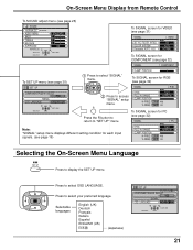
... "SIGNAL" menu. On-Screen Menu Display from Remote Control To SOUND adjust menu (see page 26) SOUND NORMALIZE NORMAL AUDIO MENU BASS TREBLE BALANCE SURROUND NORMALIZE ADJUST SELECT STANDARD 0 0 0 ON RETURN To SIGNAL screen for VIDEO (see page 31) SIGNAL [ VIDEO ] 3D Y/C FILTER (NTSC) COLOR SYSTEM Panasonic AUTO (4:3) ON AUTO NORMAL To SIGNAL screen for RGB (see page 32) SIGNAL [ RGB ] SYNC H & V 2 Press to access "SIGNAL" setup menu. To SIGNAL screen for PC (see page 32) SIGNAL [ PC ] Note: "SIGNAL" setup menu displays different setting condition for each input signals...
... "SIGNAL" menu. On-Screen Menu Display from Remote Control To SOUND adjust menu (see page 26) SOUND NORMALIZE NORMAL AUDIO MENU BASS TREBLE BALANCE SURROUND NORMALIZE ADJUST SELECT STANDARD 0 0 0 ON RETURN To SIGNAL screen for VIDEO (see page 31) SIGNAL [ VIDEO ] 3D Y/C FILTER (NTSC) COLOR SYSTEM Panasonic AUTO (4:3) ON AUTO NORMAL To SIGNAL screen for RGB (see page 32) SIGNAL [ RGB ] SYNC H & V 2 Press to access "SIGNAL" setup menu. To SIGNAL screen for PC (see page 32) SIGNAL [ PC ] Note: "SIGNAL" setup menu displays different setting condition for each input signals...

TH50PHD3U User Guide
Page 22
...) signal input during "COMPONENT" input signal mode, the mode is set to enjoy viewing the picture at its maximum size, including wide screen cinema format picture. ASPECT Controls The High Definition Plasma Display will allow you to "FULL" mode, and switching is not possible. PC OFF TIMER PLASMA DISPLAY 22 NORMAL ZOOM FULL Panasonic AUTO JUST Notes: (1) During RGB and PC input signal modes, the mode switches between "NORMAL" and "FULL" only. (2) For a 525p (480p) signal input during "COMPONENT" input signal mode, the mode switches...
...) signal input during "COMPONENT" input signal mode, the mode is set to enjoy viewing the picture at its maximum size, including wide screen cinema format picture. ASPECT Controls The High Definition Plasma Display will allow you to "FULL" mode, and switching is not possible. PC OFF TIMER PLASMA DISPLAY 22 NORMAL ZOOM FULL Panasonic AUTO JUST Notes: (1) During RGB and PC input signal modes, the mode switches between "NORMAL" and "FULL" only. (2) For a 525p (480p) signal input during "COMPONENT" input signal mode, the mode switches...

TH50PHD3U User Guide
Page 24
... DVD player is received, the picture position will shift up or down. INPUT SURROUND VOL N R PICTURE SOUND SET UP PICTURE POS. /SIZE ASPECT PC OFF TIMER PLASMA DISPLAY R Press to select H-POS/H-SIZE/V-POS/ V-SIZE/CLOCK PHASE. This picture position movement cannot be controlled by the PICTURE POS./SIZE function. 24 During "VIDEO" and "COMPONENT" input signal modes. PICTURE POS./SIZE NORMALIZE H-POS H-SIZE V-POS V-SIZE NORMAL NORMALIZE ADJUST SELECT RETURN During "RGB" and "PC" input signal modes. Press to exit adjust mode. Adjusting PICTURE...
... DVD player is received, the picture position will shift up or down. INPUT SURROUND VOL N R PICTURE SOUND SET UP PICTURE POS. /SIZE ASPECT PC OFF TIMER PLASMA DISPLAY R Press to select H-POS/H-SIZE/V-POS/ V-SIZE/CLOCK PHASE. This picture position movement cannot be controlled by the PICTURE POS./SIZE function. 24 During "VIDEO" and "COMPONENT" input signal modes. PICTURE POS./SIZE NORMALIZE H-POS H-SIZE V-POS V-SIZE NORMAL NORMALIZE ADJUST SELECT RETURN During "RGB" and "PC" input signal modes. Press to exit adjust mode. Adjusting PICTURE...
TH50PHD3U User Guide
Page 26
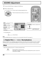
... adjust each item. SOUND Adjustment 1 Press the SOUND button to display the SOUND menu. 2 Select to reactivate sound. INPUT SURROUND VOL N R PICTURE SOUND SET UP BASS Adjusts low sounds TREBLE Adjusts high sounds BALANCE Adjusts left and right volumes SURROUND (see page 27) Helpful Hint ( N / NORMALIZE Normalization) While the "SOUND" menu is displayed, if either the N button on the remote control is pressed at any time or the (ACTION button) is changed. 26 Sound is also reactivated when power is turned...
... adjust each item. SOUND Adjustment 1 Press the SOUND button to display the SOUND menu. 2 Select to reactivate sound. INPUT SURROUND VOL N R PICTURE SOUND SET UP BASS Adjusts low sounds TREBLE Adjusts high sounds BALANCE Adjusts left and right volumes SURROUND (see page 27) Helpful Hint ( N / NORMALIZE Normalization) While the "SOUND" menu is displayed, if either the N button on the remote control is pressed at any time or the (ACTION button) is changed. 26 Sound is also reactivated when power is turned...

TH50PHD3U User Guide
Page 28
... button to switch between modes. ADVANCED SETTINGS NORMALIZE NORMAL BLACK EXTENSION W/B HIGH R W/B HIGH B W/B LOW R W/B LOW B GAMMA 0 0 0 0 0 2. 2 ADVANCED SETTINGS OFF Displays images with settings of BRIGHTNESS and PICTURE. NORMAL COOL WARM Helpful Hint ( N / NORMALIZE Normalization) While the "PICTURE" menu is pressed during "NORMALIZE", then all adjustment values are returned to the factory settings. 28 PICTURE Adjustments 1 PICTURE Press the PICTURE button on the remote control is pressed at any time or the (ACTION button) is displayed...
... button to switch between modes. ADVANCED SETTINGS NORMALIZE NORMAL BLACK EXTENSION W/B HIGH R W/B HIGH B W/B LOW R W/B LOW B GAMMA 0 0 0 0 0 2. 2 ADVANCED SETTINGS OFF Displays images with settings of BRIGHTNESS and PICTURE. NORMAL COOL WARM Helpful Hint ( N / NORMALIZE Normalization) While the "PICTURE" menu is pressed during "NORMALIZE", then all adjustment values are returned to the factory settings. 28 PICTURE Adjustments 1 PICTURE Press the PICTURE button on the remote control is pressed at any time or the (ACTION button) is displayed...

TH50PHD3U User Guide
Page 29
... adjusted for "RGB" and "PC" input signal modes. (2) You can be used as an adjustment reference. W/B HIGH R Adjusts the white balance for light blue areas. C Repeat steps A and B to a lighter color. Less More GAMMA 2.0 2.2 2.5 Down Up Notes: (1) Carry out "W/B" adjustment as night scenes and black hair. Helpful Hint ( N / NORMALIZE Normalization) While the "ADVANCED SETTINGS" menu is displayed, if either the N button on the remote control is pressed at any time...
... adjusted for "RGB" and "PC" input signal modes. (2) You can be used as an adjustment reference. W/B HIGH R Adjusts the white balance for light blue areas. C Repeat steps A and B to a lighter color. Less More GAMMA 2.0 2.2 2.5 Down Up Notes: (1) Carry out "W/B" adjustment as night scenes and black hair. Helpful Hint ( N / NORMALIZE Normalization) While the "ADVANCED SETTINGS" menu is displayed, if either the N button on the remote control is pressed at any time...

TH50PHD3U User Guide
Page 30
... on, this setting only affects NTSC input signals. 30 SIGNAL 3D Y/C FILTER (NTSC) COLOR SYSTEM Panasonic AUTO (4:3) [ VIDEO ] ON AUTO NORMAL CHANGE SELECT RETURN Press to select the "COMPONENT/RGB IN SELECT". For NTSC Video images Select the SIGNAL from adjust mode. SET UP COMPONENT/RGB-IN SELECT RGB SIGNAL OSD LANGUAGE ENGLISH (US) SELECT RETURN Press (store) button R Press to exit from the "SET UP" menu during VIDEO (S-VIDEO) input signal mode. ("SIGNAL [VIDEO]" menu is displayed.) Press to...
... on, this setting only affects NTSC input signals. 30 SIGNAL 3D Y/C FILTER (NTSC) COLOR SYSTEM Panasonic AUTO (4:3) [ VIDEO ] ON AUTO NORMAL CHANGE SELECT RETURN Press to select the "COMPONENT/RGB IN SELECT". For NTSC Video images Select the SIGNAL from adjust mode. SET UP COMPONENT/RGB-IN SELECT RGB SIGNAL OSD LANGUAGE ENGLISH (US) SELECT RETURN Press (store) button R Press to exit from the "SET UP" menu during VIDEO (S-VIDEO) input signal mode. ("SIGNAL [VIDEO]" menu is displayed.) Press to...
TH50PHD3U User Guide
Page 33
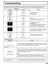
... power switch or stand-by button on the remote control.) No Picture Normal Sound If a signal with a cooling fan to display fixed images for extended periods of still pictures include logos, video games, computer images, teletext and images displayed in 4:3 mode. The display unit is not covered by rotation of the screen may be displayed for service, determine the symptoms and make a few simple checks as such is fitted with a non-applicable color system format...
... power switch or stand-by button on the remote control.) No Picture Normal Sound If a signal with a cooling fan to display fixed images for extended periods of still pictures include logos, video games, computer images, teletext and images displayed in 4:3 mode. The display unit is not covered by rotation of the screen may be displayed for service, determine the symptoms and make a few simple checks as such is fitted with a non-applicable color system format...

TH50PHD3U User Guide
Page 34
... (high impedance) EXTERNAL CONTROL TERMINAL (D-SUB9PIN) RS-232C COMPATIBLE 16W [8 W + 8 W] (10 % THD) For TY-SP50PHD3W only 34 Specifications Power Source Power Consumption Normal use Stand-by condition Power off condition Plasma Display panel Contrast Ratio Brightness Capability Screen size Operating condition Temperature Humidity Applicable signals Color System Scanning format PC signals Connection terminals AV COMPONENT/RGB PC SERIAL SPEAKERS (6 Ω) TH-50PHD3 120 V AC, 50/60 Hz Max. Amps 5.5 A 2.4 W 0.7 W Drive method AC type 50-inch, 16:9 aspect...
... (high impedance) EXTERNAL CONTROL TERMINAL (D-SUB9PIN) RS-232C COMPATIBLE 16W [8 W + 8 W] (10 % THD) For TY-SP50PHD3W only 34 Specifications Power Source Power Consumption Normal use Stand-by condition Power off condition Plasma Display panel Contrast Ratio Brightness Capability Screen size Operating condition Temperature Humidity Applicable signals Color System Scanning format PC signals Connection terminals AV COMPONENT/RGB PC SERIAL SPEAKERS (6 Ω) TH-50PHD3 120 V AC, 50/60 Hz Max. Amps 5.5 A 2.4 W 0.7 W Drive method AC type 50-inch, 16:9 aspect...


