

Brochure
Page 1
... W Power off Condition Approx. 0.3 W Approx. 0.2 W Stand-by Condition Approx. 0.5 W Approx. 0.4 W SOUND MECHANICAL Internal Speaker Output Dimensions (W x Fix 0) Weight Cabinet Color 8 0 20 W [10W. CT13-U01PF-PB-CR Panasonic ideas for life Interactive Plasma Displays 85 103 TH-85PB1U TH-103PB1U 4 • •• el Choitor-_ 5Pits linortme 1.65•50. 0 .r 5 1• 44- 103-inch /85-inch class Interactive Plasma Displays I 1 Panasonic Simulated pictures on screen. DimenSionS Cautions: This drawing is used to half when the panel...
... W Power off Condition Approx. 0.3 W Approx. 0.2 W Stand-by Condition Approx. 0.5 W Approx. 0.4 W SOUND MECHANICAL Internal Speaker Output Dimensions (W x Fix 0) Weight Cabinet Color 8 0 20 W [10W. CT13-U01PF-PB-CR Panasonic ideas for life Interactive Plasma Displays 85 103 TH-85PB1U TH-103PB1U 4 • •• el Choitor-_ 5Pits linortme 1.65•50. 0 .r 5 1• 44- 103-inch /85-inch class Interactive Plasma Displays I 1 Panasonic Simulated pictures on screen. DimenSionS Cautions: This drawing is used to half when the panel...

Brochure
Page 2
..., Easy-to switch cables when presenters change, and no worries about where in the room you are no need to inform. Plasma Panel Lifetime of About 100,000 Hours The lifetime of people. Remote Pointer Works from being blocked and helps to get the be set for Remote Pointer can be tracked when mind mapping or brainstorming. *Dedicated software is required...
..., Easy-to switch cables when presenters change, and no worries about where in the room you are no need to inform. Plasma Panel Lifetime of About 100,000 Hours The lifetime of people. Remote Pointer Works from being blocked and helps to get the be set for Remote Pointer can be tracked when mind mapping or brainstorming. *Dedicated software is required...
Operating Instructions
Page 2
...://panasonic.net Table of Contents Important Safety Notice 3 Safety Precautions 4 Accessories 7 Accessories Supply 7 Remote Control Batteries 8 Connections 9 AC cord connection and ¿xing, cable ¿xing 9 Video equipment connection 10 AUDIO OUT Terminals connection 11 VIDEO and COMPONENT / RGB IN connection ...11 HDMI connection 12 DVI-D IN connection 12 PC Input Terminals connection 13 SERIAL Terminals connection 14 Power On / Off 15 Selecting the input signal 17 Basic Controls 18 ASPECT Controls 20 Digital Zoom 21 On-Screen Menu Displays 22 Adjusting Pos./Size...
...://panasonic.net Table of Contents Important Safety Notice 3 Safety Precautions 4 Accessories 7 Accessories Supply 7 Remote Control Batteries 8 Connections 9 AC cord connection and ¿xing, cable ¿xing 9 Video equipment connection 10 AUDIO OUT Terminals connection 11 VIDEO and COMPONENT / RGB IN connection ...11 HDMI connection 12 DVI-D IN connection 12 PC Input Terminals connection 13 SERIAL Terminals connection 14 Power On / Off 15 Selecting the input signal 17 Basic Controls 18 ASPECT Controls 20 Digital Zoom 21 On-Screen Menu Displays 22 Adjusting Pos./Size...
Operating Instructions
Page 3
... compartment with the input signals could cause the picture and sound to remain on / above the set . 2) To prevent electric shock, do not expose this display. If you must not be used with this display to be placed on the Plasma Display. A replacement fuse cover can cause a permanent image retention to wobble or cause interference such as lighted candles, should be replaced, please ensure...
... compartment with the input signals could cause the picture and sound to remain on / above the set . 2) To prevent electric shock, do not expose this display. If you must not be used with this display to be placed on the Plasma Display. A replacement fuse cover can cause a permanent image retention to wobble or cause interference such as lighted candles, should be replaced, please ensure...

Operating Instructions
Page 4
... by Panasonic Corporation.) • Pedestal TY-ST85P12 (for TH-85PB1E), TY-ST103PF9 (for TH-103PB1E) • Mobile stand for Display TY-ST85PB1 (for TH-85PB1E) • Floor stand TY-ST85PF12 (for TH-85PB1E) • Wall-hanging bracket (vertical TY-WK85PV12 (for TH-85PB1E), TY-WK103PV9 (for TH-103PB1E) • Ceiling-hanging bracket TY-CE85PS12 (for TH-85PB1E), TY-CE103PS10 (for TH-103PB1E) • BNC Dual Video Terminal Board TY...
... by Panasonic Corporation.) • Pedestal TY-ST85P12 (for TH-85PB1E), TY-ST103PF9 (for TH-103PB1E) • Mobile stand for Display TY-ST85PB1 (for TH-85PB1E) • Floor stand TY-ST85PF12 (for TH-85PB1E) • Wall-hanging bracket (vertical TY-WK85PV12 (for TH-85PB1E), TY-WK103PV9 (for TH-103PB1E) • Ceiling-hanging bracket TY-CE85PS12 (for TH-85PB1E), TY-CE103PS10 (for TH-103PB1E) • BNC Dual Video Terminal Board TY...

Operating Instructions
Page 5
... made . 5 If problems occur during use the Plasma Display in Setup menu. (see page 43) When using the Plasma Display The Plasma Display is not going to operate on top of time, unplug the power supply plug from the wall outlet. • If you install the Plasma Display vertically. After checking that need to overheat, which could cause ¿re. Securely insert the power supply plug as far as no picture or no sound), or if...
... made . 5 If problems occur during use the Plasma Display in Setup menu. (see page 43) When using the Plasma Display The Plasma Display is not going to operate on top of time, unplug the power supply plug from the wall outlet. • If you install the Plasma Display vertically. After checking that need to overheat, which could cause ¿re. Securely insert the power supply plug as far as no picture or no sound), or if...
Operating Instructions
Page 11
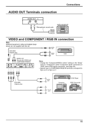
... Terminals connection Connections Stereophonic sound code line-in the "Setup" menu to "Component" (when Component signal connection) or "RGB" (when RGB signal connection). (see page 48) • Signals input to COMPONENT/RGB IN terminals correspond to Sync on G or Sync on Y. RCA-BNC Adapter plug VIDEO OUT L AUDIO R OUT VCR AUDIO L-R: Shared with VIDEO and COMPONENT/RGB IN Notes: • Change the "Component/RGB-in select" setting in audio equipment VIDEO and COMPONENT / RGB IN connection...
... Terminals connection Connections Stereophonic sound code line-in the "Setup" menu to "Component" (when Component signal connection) or "RGB" (when RGB signal connection). (see page 48) • Signals input to COMPONENT/RGB IN terminals correspond to Sync on G or Sync on Y. RCA-BNC Adapter plug VIDEO OUT L AUDIO R OUT VCR AUDIO L-R: Shared with VIDEO and COMPONENT/RGB IN Notes: • Change the "Component/RGB-in select" setting in audio equipment VIDEO and COMPONENT / RGB IN connection...
Operating Instructions
Page 15
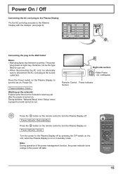
... 9) Connecting the plug to turn the Plasma Display on. Power Indicator: Red (standby) Press the button on the remote control to the Wall Outlet Notes: • Main plug types vary between countries. Power Indicator: Green [Starting up just after the power is turned on. Right side surface Main Power On / Off Switch Remote Control Power Indicator Sensor Press the button on the remote control to start up the network] It takes some time for the network to turn the set . switch...
... 9) Connecting the plug to turn the Plasma Display on. Power Indicator: Red (standby) Press the button on the remote control to the Wall Outlet Notes: • Main plug types vary between countries. Power Indicator: Green [Starting up just after the power is turned on. Right side surface Main Power On / Off Switch Remote Control Power Indicator Sensor Press the button on the remote control to start up the network] It takes some time for the network to turn the set . switch...
Operating Instructions
Page 17
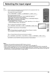
... equipment which has been connected to image retention. 17 Input signals will change as "RGB" depending on the plasma display panel when a still picture is installed: ENTER / PC NETWORK SLOT INPUT VIDEO COMPONENT HDMI DVI +/ VOL -/ MENU SLOT INPUT: Input terminal in PC IN. NETWORK: Network input terminal in the Options menu. (see page 48) When an optional Terminal Board is kept on the unit. • Outputs the sound as set in "Audio input select" in LAN or...
... equipment which has been connected to image retention. 17 Input signals will change as "RGB" depending on the plasma display panel when a still picture is installed: ENTER / PC NETWORK SLOT INPUT VIDEO COMPONENT HDMI DVI +/ VOL -/ MENU SLOT INPUT: Input terminal in PC IN. NETWORK: Network input terminal in the Options menu. (see page 48) When an optional Terminal Board is kept on the unit. • Outputs the sound as set in "Audio input select" in LAN or...
Operating Instructions
Page 19
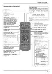
..., from Standby mode. Press again to stand-by after a ¿xed period. N button (see page 25, 26, 27, 31) POSITION buttons INPUT button Press to select Input signal sequentially. (see page 17) ECO MODE (ECO) Press to change the ECO MODE setup status. (see page 40) FUNCTION buttons (FUNCTION) (see page 42) Basic Controls OFF TIMER button The Plasma Display can be plugged into the wall outlet and turned on at the power switch...
..., from Standby mode. Press again to stand-by after a ¿xed period. N button (see page 25, 26, 27, 31) POSITION buttons INPUT button Press to select Input signal sequentially. (see page 17) ECO MODE (ECO) Press to change the ECO MODE setup status. (see page 40) FUNCTION buttons (FUNCTION) (see page 42) Basic Controls OFF TIMER button The Plasma Display can be plugged into the wall outlet and turned on at the power switch...
Operating Instructions
Page 23
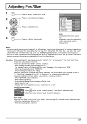
... DVD player is "RGB". • When inputting a digital signal (HDMI/DVI): A PC format signal enables this setting is enabled only if "Over Scan" (see page 24) is "Off" or "1:1 Pixel Mode" (see page 54), automatic position adjustment starts: • When the display power is turned ON. • When the input signal is set to "On" Using Remote Control When on the input signal and the display mode. Adjustable items differ depending on the remote control is pressed, "Auto Setup" will not work...
... DVD player is "RGB". • When inputting a digital signal (HDMI/DVI): A PC format signal enables this setting is enabled only if "Over Scan" (see page 24) is "Off" or "1:1 Pixel Mode" (see page 54), automatic position adjustment starts: • When the display power is turned ON. • When the input signal is set to "On" Using Remote Control When on the input signal and the display mode. Adjustable items differ depending on the remote control is pressed, "Auto Setup" will not work...
Operating Instructions
Page 24
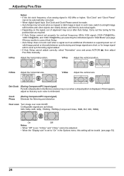
... Component/PC input signal) Periodic striped pattern interference (noise) may occur when a striped pattern is set , "H-Size" and "V-Size" cannot be adjusted. • When the "Display size" is displayed. Adjust the horizontal position. Over scan Turn image over scan On/Off. Adjusting Pos./Size H-Pos Notes: • If the dot clock frequency of alignment may occur after Auto Setup. In such case, switch to "On" in correct Auto Setup. • Auto Setup does not work when...
... Component/PC input signal) Periodic striped pattern interference (noise) may occur when a striped pattern is set , "H-Size" and "V-Size" cannot be adjusted. • When the "Display size" is displayed. Adjust the horizontal position. Over scan Turn image over scan On/Off. Adjusting Pos./Size H-Pos Notes: • If the dot clock frequency of alignment may occur after Auto Setup. In such case, switch to "On" in correct Auto Setup. • Auto Setup does not work when...
Operating Instructions
Page 34
...) • When using the electronic pen, adjust "Pos./Size" so that is displayed in "Setup" menu and press button. Touch Only: Contact-type Touch Pen Touch & Remote: Contact-type Touch Pen and remote pointer SLOT INPUT - Pos./Size menu Picture menu Setup menu Signal Extended life settings MULTI DISPLAY Setup Portrait Setup Options menu ASPECT Controls 1:1 Pixel Mode: On Over scan: Off Picture Mode: Fixed to "Normal" (see page 26) FRAME CREATION: Off Picture Mode: Fixed to "On", the mode becomes Touch...
...) • When using the electronic pen, adjust "Pos./Size" so that is displayed in "Setup" menu and press button. Touch Only: Contact-type Touch Pen Touch & Remote: Contact-type Touch Pen and remote pointer SLOT INPUT - Pos./Size menu Picture menu Setup menu Signal Extended life settings MULTI DISPLAY Setup Portrait Setup Options menu ASPECT Controls 1:1 Pixel Mode: On Over scan: Off Picture Mode: Fixed to "Normal" (see page 26) FRAME CREATION: Off Picture Mode: Fixed to "On", the mode becomes Touch...
Operating Instructions
Page 40
... to "Auto", "Component / RGB-in "Setup" menu and press button. When this function is set to "Enable", the power supply of power consumption reduction is individually set. Note: In Touch Pen mode, the sensor function is individually set to turn the power on or off : Enable PC Power management: On Using Remote Control When is pressed, the "ECO Mode" setting ECO Mode On changes. When pictures (sync signal) are subsequently detected: ĺ Power is turned on the...
... to "Auto", "Component / RGB-in "Setup" menu and press button. When this function is set to "Enable", the power supply of power consumption reduction is individually set. Note: In Touch Pen mode, the sensor function is individually set to turn the power on or off : Enable PC Power management: On Using Remote Control When is pressed, the "ECO Mode" setting ECO Mode On changes. When pictures (sync signal) are subsequently detected: ĺ Power is turned on the...

Operating Instructions
Page 42
... using the "Wireless Manager". FUNCTION1 button: Touch-Pen FUNCTION2 button: Scrolling bar ECO Mode settings / Signal / On/Off Timer Setup The menu is displayed. After 15 minutes, the display enters standby mode. When a Terminal Board with dual input terminals is not displayed. Computer Search Switch to the FUNCTION button. The list of the button. AV Mute Mutes the audio and video. On: Press the FUNCTION button to display the function list of connectable computers on the network is installed...
... using the "Wireless Manager". FUNCTION1 button: Touch-Pen FUNCTION2 button: Scrolling bar ECO Mode settings / Signal / On/Off Timer Setup The menu is displayed. After 15 minutes, the display enters standby mode. When a Terminal Board with dual input terminals is not displayed. Computer Search Switch to the FUNCTION button. The list of the button. AV Mute Mutes the audio and video. On: Press the FUNCTION button to display the function list of connectable computers on the network is installed...
Operating Instructions
Page 48
... optional board is installed. • Make setting of the selected input terminal (COMPONENT/RGB IN or PC IN). YUV / RGB-in select Component RGB Select to match the signals from the source connected to the Component / RGB or PC input terminals. Y, PB, PR signals "Component" RGB signals "RGB" Note: Make setting of the selected input terminal (SLOT or DVI-D IN). 48 Setup for Input Signals Component...
... optional board is installed. • Make setting of the selected input terminal (COMPONENT/RGB IN or PC IN). YUV / RGB-in select Component RGB Select to match the signals from the source connected to the Component / RGB or PC input terminals. Y, PB, PR signals "Component" RGB signals "RGB" Note: Make setting of the selected input terminal (SLOT or DVI-D IN). 48 Setup for Input Signals Component...
Operating Instructions
Page 49
...". Switch the setting to the unit. On Off Note: When On, this menu when the moving image looks unnatural during "Component" input signal. • XGA Mode This menu is displayed when the input signal is set on the input signal type, an optional Terminal Board may in "Setup" menu and press button. If the picture is installed to suit the input signal for each adjustment (such as "Auto Setup") on the angle of view or display resolution condition...
...". Switch the setting to the unit. On Off Note: When On, this menu when the moving image looks unnatural during "Component" input signal. • XGA Mode This menu is displayed when the input signal is set on the input signal type, an optional Terminal Board may in "Setup" menu and press button. If the picture is installed to suit the input signal for each adjustment (such as "Auto Setup") on the angle of view or display resolution condition...

Operating Instructions
Page 52
... input signal when the unit is "Off". On: Sets your preferred maximum volume. Remote ID Off Serial ID Off Display size Off 4 Press to adjust the volume when the unit is "On", the volume can hear the changed volume regardless of "Component/RGB-in select". (see page 48) Notes: • Only the adjusted signal is on . Slot power O f f Power On Screen Delay Off Clock Display Off All Aspect Off Auto Setup Manual...
... input signal when the unit is "Off". On: Sets your preferred maximum volume. Remote ID Off Serial ID Off Display size Off 4 Press to adjust the volume when the unit is "On", the volume can hear the changed volume regardless of "Component/RGB-in select". (see page 48) Notes: • Only the adjusted signal is on . Slot power O f f Power On Screen Delay Off Clock Display Off All Aspect Off Auto Setup Manual...
Operating Instructions
Page 53
... in standby mode. (Power Indicator : red/orange) On: Power returns in power On. (Power Indicator : green) Note: When using ID remote control. About the setting method, please refer to each ID number of "Component/RGB-in select". (see page 48) Notes: • Only the adjusted signal is displayed (see page 45) and "ID select" (above-mentioned). Sets the panel ID Control. Off: Disables external control by the ID. Off SLOT INPUT*1 VIDEO COMPONENT*2 HDMI DVI...
... in standby mode. (Power Indicator : red/orange) On: Power returns in power On. (Power Indicator : green) Note: When using ID remote control. About the setting method, please refer to each ID number of "Component/RGB-in select". (see page 48) Notes: • Only the adjusted signal is displayed (see page 45) and "ID select" (above-mentioned). Sets the panel ID Control. Off: Disables external control by the ID. Off SLOT INPUT*1 VIDEO COMPONENT*2 HDMI DVI...
Operating Instructions
Page 59
... by button on the remote control.) Check if speakers are connected properly. Due to the characteristics of the system used . (The unit cannot be heard from ¿xed image use . The plasma display panel is manufactured using a video software program (such as this can be missing picture elements or have not, whether they were inserted properly. are no adverse effects on the type of input signal. Check The screen...
... by button on the remote control.) Check if speakers are connected properly. Due to the characteristics of the system used . (The unit cannot be heard from ¿xed image use . The plasma display panel is manufactured using a video software program (such as this can be missing picture elements or have not, whether they were inserted properly. are no adverse effects on the type of input signal. Check The screen...


