
Installation Instructions
Page 1
... III ( I -Joist Mounting ) Installation IV( Between Joist Mounting ) Installation V ( Wooden Header ) Installation VI ( In Existing Construction ) Maintenance Practical Guide to install, operate or service the Panasonic Ventilating Fan. Failure to comply with instructions could result in personal injury and/or property damage. INSTALLATION INSTRUCTIONS Ventilating...
... III ( I -Joist Mounting ) Installation IV( Between Joist Mounting ) Installation V ( Wooden Header ) Installation VI ( In Existing Construction ) Maintenance Practical Guide to install, operate or service the Panasonic Ventilating Fan. Failure to comply with instructions could result in personal injury and/or property damage. INSTALLATION INSTRUCTIONS Ventilating...

Installation Instructions
Page 2
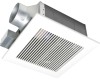
... is a spring-loaded, quickremove type. It also incorporates a thermal-cutoff for preventing counterfiow is designed to reduce noise. The grille covering the fan body is used to have an extended service life with dolphin-shaped blades driven by a capacitor motor. A damper for safety. The motor is...2X8) €) ) 2 Screw II (ST4.2X10) CC17 2 Suspension bracket I o 1 Suspension bracket II 1 Suspension bracket III 1 3 inches adaptor connector 1 (optional part) DESCRIPTION These Panasonic ventilation fans models use a sirocco fan with reduced energy consumption.
... is a spring-loaded, quickremove type. It also incorporates a thermal-cutoff for preventing counterfiow is designed to reduce noise. The grille covering the fan body is used to have an extended service life with dolphin-shaped blades driven by a capacitor motor. A damper for safety. The motor is...2X8) €) ) 2 Screw II (ST4.2X10) CC17 2 Suspension bracket I o 1 Suspension bracket II 1 Suspension bracket III 1 3 inches adaptor connector 1 (optional part) DESCRIPTION These Panasonic ventilation fans models use a sirocco fan with reduced energy consumption.

Installation Instructions
Page 3
... 7/8 (301) 0 8 7 ® 13 (330) 13 4 3/8 ( 10) 11 5 5/8 (141) • 10 1/4 (261) 16 1/8 (410) No. Part name 8 Motor 9 Suspension bracket 10 Junction box 11 Damper 12 Fan body 13 Bracket cover (For 16 inches on center joists, only use suspension bracket I, for 19.2 inches on center joists, only use suspension bracket III...
... 7/8 (301) 0 8 7 ® 13 (330) 13 4 3/8 ( 10) 11 5 5/8 (141) • 10 1/4 (261) 16 1/8 (410) No. Part name 8 Motor 9 Suspension bracket 10 Junction box 11 Damper 12 Fan body 13 Bracket cover (For 16 inches on center joists, only use suspension bracket I, for 19.2 inches on center joists, only use suspension bracket III...
Installation Instructions
Page 4
...safety codes, as well as shown in a GFCI protected branch circuit, 0 Prohibition 0 Prohibition Prohibition Fig. Do not install this ventilating fan where interior room temperature may exceed 104°F (40°C). 2. Follow all parts are present. Provide suction parts with proper ventilation.... FV-05VF2 3 0.5 4 0.4 3 0.8 FV-08VF2 Exhaust 120 60 4 0.8 FV-11VF2 3 1.5 4 1.5 Specifications are based on or near the fan, motor or junction box. 5. Refer to the Supplied Accessories list to verify that the electric service supply voltage is UL listed for use over a bathtub...
...safety codes, as well as shown in a GFCI protected branch circuit, 0 Prohibition 0 Prohibition Prohibition Fig. Do not install this ventilating fan where interior room temperature may exceed 104°F (40°C). 2. Follow all parts are present. Provide suction parts with proper ventilation.... FV-05VF2 3 0.5 4 0.4 3 0.8 FV-08VF2 Exhaust 120 60 4 0.8 FV-11VF2 3 1.5 4 1.5 Specifications are based on or near the fan, motor or junction box. 5. Refer to the Supplied Accessories list to verify that the electric service supply voltage is UL listed for use over a bathtub...

Installation Instructions
Page 5
...C. Follow the heating equipment manufacturer's guideline and safety standards such as a tag, to prevent power from a tub or shower. Ducted fans must always be reached from being switched on accidentally. These models are UL listed for Heating Refrigeration and Air Conditioning Engineers (ASHRAE) and...must be installed in a ceiling thermally insulated to a value greater than R40. (This is needed for use in Canada only.) WIRING DIAGRAM Fan body Motor Red White Junction box 1T Capacitor White - I Live Green Greeni Earth ground 0 Earth ground Power Supply AC120V 60Hz 5 E....
...C. Follow the heating equipment manufacturer's guideline and safety standards such as a tag, to prevent power from a tub or shower. Ducted fans must always be reached from being switched on accidentally. These models are UL listed for Heating Refrigeration and Air Conditioning Engineers (ASHRAE) and...must be installed in a ceiling thermally insulated to a value greater than R40. (This is needed for use in Canada only.) WIRING DIAGRAM Fan body Motor Red White Junction box 1T Capacitor White - I Live Green Greeni Earth ground 0 Earth ground Power Supply AC120V 60Hz 5 E....
Installation Instructions
Page 6
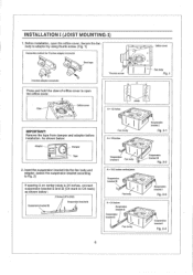
... mark) as shown below : Adaptor . = I Fig. 2-1 A= 16 inches • . . A = 19.2 inches vertical joists Suspension bracket M - Suspension bracket I ) 1. C) '. INSTALLATION I (JOIST MOUNTING-I Fig. 2-4 6 As shown below : 2 Screw I Fan body :t. .:. ' ' Suspension bracket III Fig. 2-2 2. V 1 ... IMPORTANT: Remove the tape from damper and adaptor before installation. Before installation, open the orifice cover. ® .. -.0 ..• Orifice cover...
... mark) as shown below : Adaptor . = I Fig. 2-1 A= 16 inches • . . A = 19.2 inches vertical joists Suspension bracket M - Suspension bracket I ) 1. C) '. INSTALLATION I (JOIST MOUNTING-I Fig. 2-4 6 As shown below : 2 Screw I Fan body :t. .:. ' ' Suspension bracket III Fig. 2-2 2. V 1 ... IMPORTANT: Remove the tape from damper and adaptor before installation. Before installation, open the orifice cover. ® .. -.0 ..• Orifice cover...
Installation Instructions
Page 7
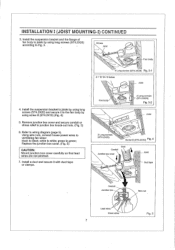
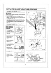
...(Fig. 5) CAUTION: Mount junction box cover carefully so that lead wires are not pinched. 7. Install the suspension bracket and the flange of fan body to the fan body by using long screws (ST4.2X20) and secure it with duct tape or clamps. Install a duct and secure it to joists by... using screw II (ST4.2X10) (Fig. 4) 5. Refer to green; Fan body 2 Long screws > (ST4.2X20) Fig. 3-2 Joist 2 Long screws (ST4.2X20) O CD 0 Screw D(ST4.2X10) Fig. 4 Conduit Junction box cover Duct - Remove...
...(Fig. 5) CAUTION: Mount junction box cover carefully so that lead wires are not pinched. 7. Install the suspension bracket and the flange of fan body to the fan body by using long screws (ST4.2X20) and secure it with duct tape or clamps. Install a duct and secure it to joists by... using screw II (ST4.2X10) (Fig. 4) 5. Refer to green; Fan body 2 Long screws > (ST4.2X20) Fig. 3-2 Joist 2 Long screws (ST4.2X20) O CD 0 Screw D(ST4.2X10) Fig. 4 Conduit Junction box cover Duct - Remove...
Installation Instructions
Page 8
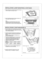
... before starting installation. Adaptor 2. Ceiling g.#1 • Grille Fig. 7 INSTALLATION II (JOIST MOUNTING-II) 1. Insert the suspension bracket into fan body (refering to spacing A as shown and mount grille to fan body. (Fig. 7) 7 Ceiling inches (mm) Slot (irk \ \ Fig. 6 Mounting spring Note: Suitable for the thickness of Installation I, page 6) 2 Long screws \ (ST4.2X20...
... before starting installation. Adaptor 2. Ceiling g.#1 • Grille Fig. 7 INSTALLATION II (JOIST MOUNTING-II) 1. Insert the suspension bracket into fan body (refering to spacing A as shown and mount grille to fan body. (Fig. 7) 7 Ceiling inches (mm) Slot (irk \ \ Fig. 6 Mounting spring Note: Suitable for the thickness of Installation I, page 6) 2 Long screws \ (ST4.2X20...
Installation Instructions
Page 9
...6. Insert the blower into joists. (Fig. 9) 5. Remove blower section. (Fig. 12-2) 3. Secure the adaptor to fan body by using thumb screw and plug connector to fan body by using screw It(ST4,2X10) in vertical direction (Fig. 11) 8. When mounting body and blower separately 1, ... connector to 9 of page 8. 4 Screws Adaptor O O 0 0 e Fig. 12-1 Blower Joist Conduit Junction box cover Duct • Duct tape (c) Slots Fan body Adaptor claws Fig. 9 4. Follow step 8 to receptacle (Fig, 10) C Joist Fig. 12-3 4 Screws Screw driver Fig. 12-4 Receptacle Thumb Plug connector...
...6. Insert the blower into joists. (Fig. 9) 5. Remove blower section. (Fig. 12-2) 3. Secure the adaptor to fan body by using thumb screw and plug connector to fan body by using screw It(ST4,2X10) in vertical direction (Fig. 11) 8. When mounting body and blower separately 1, ... connector to 9 of page 8. 4 Screws Adaptor O O 0 0 e Fig. 12-1 Blower Joist Conduit Junction box cover Duct • Duct tape (c) Slots Fan body Adaptor claws Fig. 9 4. Follow step 8 to receptacle (Fig, 10) C Joist Fig. 12-3 4 Screws Screw driver Fig. 12-4 Receptacle Thumb Plug connector...

Installation Instructions
Page 10
... ts, • . Before installation, open the orifice cover. Insert the suspension bracket into the bracket cover of adaptor side and the back of the fan body. (Fig.15) (select the suspension bracket according to adaptor by using thumb screw. (Fig. 1 of I -joist. c. ° •... joist Suspension bracket M OM ill ft . Before installation, open the orifice cover. Secure the fan body to spacing A as shown below) A A___ /L._ 16 Inches and 19,2 f inches horizontal joist e.-. Connect the fan body to adaptor by using thumb screw. (Fig.1 of installation I (page 7, page 8) to...
... ts, • . Before installation, open the orifice cover. Insert the suspension bracket into the bracket cover of adaptor side and the back of the fan body. (Fig.15) (select the suspension bracket according to adaptor by using thumb screw. (Fig. 1 of I -joist. c. ° •... joist Suspension bracket M OM ill ft . Before installation, open the orifice cover. Secure the fan body to spacing A as shown below) A A___ /L._ 16 Inches and 19,2 f inches horizontal joist e.-. Connect the fan body to adaptor by using thumb screw. (Fig.1 of installation I (page 7, page 8) to...
Installation Instructions
Page 11
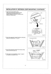
... Junction box 4. Secure the suspension bracket to fan body by using screw II (ST4.2X10) (Fig. 18) 6. Secure the suspension bracket to joists by using long screws (ST4.2X20) (Fig. 17, Fig. 18) A .... 11 Fig. 17 4 Long screws 2 Screw II (ST4.2X20) (ST4.2X10) Joist Fig. 18 INSTALLATION IV ( BETWEEN JOIST MOUNTING ) CONTINUED 3, Insert the fan body between joists. Make sure the fan body is level and square Joists (perpendicular) with the joists.(Fig. 16) Keep the distance B (7/8 inch, 21.6mm) for the thickness of...
... Junction box 4. Secure the suspension bracket to fan body by using screw II (ST4.2X10) (Fig. 18) 6. Secure the suspension bracket to joists by using long screws (ST4.2X20) (Fig. 17, Fig. 18) A .... 11 Fig. 17 4 Long screws 2 Screw II (ST4.2X20) (ST4.2X10) Joist Fig. 18 INSTALLATION IV ( BETWEEN JOIST MOUNTING ) CONTINUED 3, Insert the fan body between joists. Make sure the fan body is level and square Joists (perpendicular) with the joists.(Fig. 16) Keep the distance B (7/8 inch, 21.6mm) for the thickness of...
Installation Instructions
Page 12
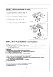
... ) 1, Installation in Installation II. Follow step 5 to Fig. 6 of page 8. (6) Install ventilating fan. 2. Fan body inches (mm) Header. Installing the ventilating fan in an existing building requires an accessible area (attic or crawl space) above planning installation location to be sure...access at a location that : 1. Duct work and wiring before installation. Wiring can be run to Fig. 6 of page 8. (3) Install ventilating fan. 12 Install the fan body and secure it by using nails or screws. 0 7 (27s 3. Joist 4 3l4 (376) t Adaptor Fig. 19 Circular duct II 38...
... ) 1, Installation in Installation II. Follow step 5 to Fig. 6 of page 8. (6) Install ventilating fan. 2. Fan body inches (mm) Header. Installing the ventilating fan in an existing building requires an accessible area (attic or crawl space) above planning installation location to be sure...access at a location that : 1. Duct work and wiring before installation. Wiring can be run to Fig. 6 of page 8. (3) Install ventilating fan. 12 Install the fan body and secure it by using nails or screws. 0 7 (27s 3. Joist 4 3l4 (376) t Adaptor Fig. 19 Circular duct II 38...
Installation Instructions
Page 13
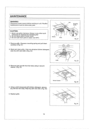
...Fig, 21 Grille 3. MAINTENANCE WARNING: Disconnect power source before working on unit, Routine maintenance must be done every year. Remove dust and dirt from fan body. Replace grille. 0 13 Fig. 23 Fig. 24 Gloves Grille 1. CAUTION: 1, Never use petrol, benzene, thinner or any dirt from... fan body using a vacuum cleaner. (Fig. 23) Fig. 22 Vacuum cleaner 4. Remove grille. (Squeeze mounting spring and pull down carefully.) (Fig. 21) 2, Wash and clean ...
...Fig, 21 Grille 3. MAINTENANCE WARNING: Disconnect power source before working on unit, Routine maintenance must be done every year. Remove dust and dirt from fan body. Replace grille. 0 13 Fig. 23 Fig. 24 Gloves Grille 1. CAUTION: 1, Never use petrol, benzene, thinner or any dirt from... fan body using a vacuum cleaner. (Fig. 23) Fig. 22 Vacuum cleaner 4. Remove grille. (Squeeze mounting spring and pull down carefully.) (Fig. 21) 2, Wash and clean ...
Installation Instructions
Page 14
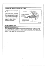
...Warning Concerning Removal of flexible duct helps alignment and absorbs Insulation. No service information is a common problem with backdraft flap(s). Panasonic fans and fan/light combination units do not create enough ambient heat to be subjected to these limitations. Short piece of Covers. The unit ... caulk box to duct. 2-3 ft straight run before elbow. Dryer-hood type vent with recessed light fixtures or some competitors' fan/light combinations. sound. Our efficient, cool-running motors and our fluorescent bulbs do not create excessive heat that is provided for ...
...Warning Concerning Removal of flexible duct helps alignment and absorbs Insulation. No service information is a common problem with backdraft flap(s). Panasonic fans and fan/light combination units do not create enough ambient heat to be subjected to these limitations. Short piece of Covers. The unit ... caulk box to duct. 2-3 ft straight run before elbow. Dryer-hood type vent with recessed light fixtures or some competitors' fan/light combinations. sound. Our efficient, cool-running motors and our fluorescent bulbs do not create excessive heat that is provided for ...
