
Installation Instructions
Page 1
... Accessories Description Dimensions Specifications Unpacking General Safety Information Wiring Diagram Installation I ( Joist Mounting-I ) Installation II ( Joist Mounting-II ) Install tion III ( I -Joist Mounting ) Installation IV( Between Joist Mounting ) Installation V ( Wooden Header ) Installation VI ( In Existing Construction ) Maintenance Practical Guide to comply with instructions could result in personal injury and/or property damage. INSTALLATION INSTRUCTIONS Ventilating Fan FV-05VF2 FV-08VF2 FV-11VF2 Panasonid READ AND SAVE THESE INSTRUCTIONS. Failure to Installation...
... Accessories Description Dimensions Specifications Unpacking General Safety Information Wiring Diagram Installation I ( Joist Mounting-I ) Installation II ( Joist Mounting-II ) Install tion III ( I -Joist Mounting ) Installation IV( Between Joist Mounting ) Installation V ( Wooden Header ) Installation VI ( In Existing Construction ) Maintenance Practical Guide to comply with instructions could result in personal injury and/or property damage. INSTALLATION INSTRUCTIONS Ventilating Fan FV-05VF2 FV-08VF2 FV-11VF2 Panasonid READ AND SAVE THESE INSTRUCTIONS. Failure to Installation...

Installation Instructions
Page 2
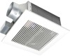
... an extended service life with dolphin-shaped blades driven by a capacitor motor. SUPPLIED ACCESSORIES FV-05VF2 FV-08VF2 FV-11VF2 Part name Appearance Quantity Grille r-" 1 Long screw (ST4.2X20) 0 6 Thumb screw (1P 1 Screw I (ST4.2X8) €) ) 2 Screw II (ST4.2X10) CC17 2 Suspension bracket I o 1 Suspension bracket II 1 Suspension bracket III 1 3 inches adaptor connector 1 (optional part) DESCRIPTION These Panasonic ventilation fans models use a sirocco fan with reduced energy consumption. The grille covering the fan body...
... an extended service life with dolphin-shaped blades driven by a capacitor motor. SUPPLIED ACCESSORIES FV-05VF2 FV-08VF2 FV-11VF2 Part name Appearance Quantity Grille r-" 1 Long screw (ST4.2X20) 0 6 Thumb screw (1P 1 Screw I (ST4.2X8) €) ) 2 Screw II (ST4.2X10) CC17 2 Suspension bracket I o 1 Suspension bracket II 1 Suspension bracket III 1 3 inches adaptor connector 1 (optional part) DESCRIPTION These Panasonic ventilation fans models use a sirocco fan with reduced energy consumption. The grille covering the fan body...

Installation Instructions
Page 3
... 4 3/8 ( 10) 11 5 5/8 (141) • 10 1/4 (261) 16 1/8 (410) No. Part name 8 Motor 9 Suspension bracket 10 Junction box 11 Damper 12 Fan body 13 Bracket cover (For 16 inches on center joists, only use suspension bracket I, for 19.2 inches on center joists, only use suspension bracket III, If more than 19.2 inches on center,use suspension bracket II & III.) 3 Part name 1 Grille 2 Orifice cover 3 Junction box cover 4 Adaptor 5 Adaptor connector 6 Orifice 7 Blade No.
... 4 3/8 ( 10) 11 5 5/8 (141) • 10 1/4 (261) 16 1/8 (410) No. Part name 8 Motor 9 Suspension bracket 10 Junction box 11 Damper 12 Fan body 13 Bracket cover (For 16 inches on center joists, only use suspension bracket I, for 19.2 inches on center joists, only use suspension bracket III, If more than 19.2 inches on center,use suspension bracket II & III.) 3 Part name 1 Grille 2 Orifice cover 3 Junction box cover 4 Adaptor 5 Adaptor connector 6 Orifice 7 Blade No.
Installation Instructions
Page 4
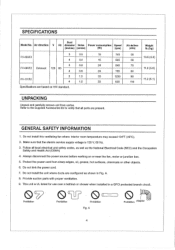
... local electrical and safety codes, as well as shown in a GFCI protected branch circuit, 0 Prohibition 0 Prohibition Prohibition Fig. Protect the power cord from carton. Provide suction parts with proper ventilation. 9. SPECIFICATIONS Duct Model No, Air direction V Hz diameter Noise Power consumption Speed (inches) (sones) (W) (rpm) FV-05VF2 3 0.5 4 0.4 3 0.8 FV-08VF2 Exhaust 120 60 4 0.8 FV-11VF2 3 1.5 4 1.5 Specifications are based on or near the fan, motor or junction box. 5. GENERAL...
... local electrical and safety codes, as well as shown in a GFCI protected branch circuit, 0 Prohibition 0 Prohibition Prohibition Fig. Protect the power cord from carton. Provide suction parts with proper ventilation. 9. SPECIFICATIONS Duct Model No, Air direction V Hz diameter Noise Power consumption Speed (inches) (sones) (W) (rpm) FV-05VF2 3 0.5 4 0.4 3 0.8 FV-08VF2 Exhaust 120 60 4 0.8 FV-11VF2 3 1.5 4 1.5 Specifications are based on or near the fan, motor or junction box. 5. GENERAL...

Installation Instructions
Page 5
... is needed for installation in accordance with all applicable codes and standards, including fire-rated construction. GENERAL SAFETY INFORMATION CONTINUED CAUTION: 1. Do not use to the outdoors. B) 3. C. These models are UL listed for use only. For general ventilating use in cooking area. (Fig. When,cutting or drilling into wall or ceiling, do not damage electrical wiring and other hidden utilities. NEVER place a switch where it...
... is needed for installation in accordance with all applicable codes and standards, including fire-rated construction. GENERAL SAFETY INFORMATION CONTINUED CAUTION: 1. Do not use to the outdoors. B) 3. C. These models are UL listed for use only. For general ventilating use in cooking area. (Fig. When,cutting or drilling into wall or ceiling, do not damage electrical wiring and other hidden utilities. NEVER place a switch where it...
Installation Instructions
Page 6
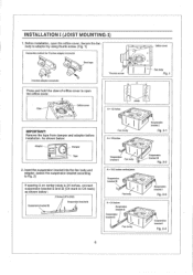
... by using thumb screw, (Fig. 1) Connection method for 3 Inches adaptor connector • e Duct tape 0 3 inches adaptor connector O 0 4-4 Orifice cover Thumb screw I Damper Tape Joists A = 12 inches , .. Secure the fan body to open the orifice cover. Fan body Suspension bracket I Fig. 2-3 A = 24 inches Suspension bracket DI Suspension () bracket II • Fan body .. . - - I Fan body ' Suspension bracket I Fig. 2-1 A= 16 inches • . . IMPORTANT: Remove the tape from damper and adaptor before installation. Suspension bracket I Fan body...
... by using thumb screw, (Fig. 1) Connection method for 3 Inches adaptor connector • e Duct tape 0 3 inches adaptor connector O 0 4-4 Orifice cover Thumb screw I Damper Tape Joists A = 12 inches , .. Secure the fan body to open the orifice cover. Fan body Suspension bracket I Fig. 2-3 A = 24 inches Suspension bracket DI Suspension () bracket II • Fan body .. . - - I Fan body ' Suspension bracket I Fig. 2-1 A= 16 inches • . . IMPORTANT: Remove the tape from damper and adaptor before installation. Suspension bracket I Fan body...
Installation Instructions
Page 7
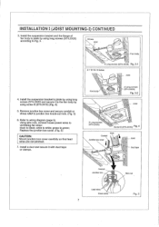
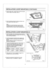
... Fan body 4 Long screws (ST4.2X20) Fig. 3-1 A = 10 1/4-12 inches Joist 4. Using wire nuts, connect house power wires to ventilating fan wires: black to white; white to black; green to junction box knock-out hole. (Fig. 5) 6. Install the suspension bracket to joists by using long screws (ST4.2X20) according to joists by using screw II (ST4.2X10) (Fig. 4) 5. Replace the junction box cover. (Fig. 5) CAUTION: Mount junction box cover carefully so that lead wires are not pinched. 7. Remove junction box cover...
... Fan body 4 Long screws (ST4.2X20) Fig. 3-1 A = 10 1/4-12 inches Joist 4. Using wire nuts, connect house power wires to ventilating fan wires: black to white; white to black; green to junction box knock-out hole. (Fig. 5) 6. Install the suspension bracket to joists by using long screws (ST4.2X20) according to joists by using screw II (ST4.2X10) (Fig. 4) 5. Replace the junction box cover. (Fig. 5) CAUTION: Mount junction box cover carefully so that lead wires are not pinched. 7. Remove junction box cover...
Installation Instructions
Page 8
... Fig. 7 INSTALLATION II (JOIST MOUNTING-II) 1. Ceiling hole should be aligned with solid-state speed controls. Solid-state speed controls may cause harmonic distortion which can cause a motor humming noise. Adaptor 2. Insert the suspension bracket into fan body (refering to joists by using long screws (ST4.2X20) (Fig. 8) Keep the distance B (7/8 inch, 21.6mm) for use with the edge of the Installation I & II 2 Long screws (ST4.2X20) inches (mm...
... Fig. 7 INSTALLATION II (JOIST MOUNTING-II) 1. Ceiling hole should be aligned with solid-state speed controls. Solid-state speed controls may cause harmonic distortion which can cause a motor humming noise. Adaptor 2. Insert the suspension bracket into fan body (refering to joists by using long screws (ST4.2X20) (Fig. 8) Keep the distance B (7/8 inch, 21.6mm) for use with the edge of the Installation I & II 2 Long screws (ST4.2X20) inches (mm...
Installation Instructions
Page 9
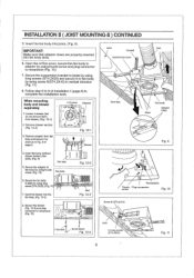
.... 6, Open the orifice cover, secure the fan body to adaptor by using long screws (ST4.2X20) and secure it to joists as in vertical direction (Fig. 11) 8. Remove blower section. (Fig. 12-2) 3. Secure the blower. (Fig, 12-4) and plug connector to complete the installation work. Follow step 8 to 9 of page 8. 4 Screws Adaptor O O 0 0 e Fig. 12-1 Blower Joist Conduit Junction box cover Duct • Duct...
.... 6, Open the orifice cover, secure the fan body to adaptor by using long screws (ST4.2X20) and secure it to joists as in vertical direction (Fig. 11) 8. Remove blower section. (Fig. 12-2) 3. Secure the blower. (Fig, 12-4) and plug connector to complete the installation work. Follow step 8 to 9 of page 8. 4 Screws Adaptor O O 0 0 e Fig. 12-1 Blower Joist Conduit Junction box cover Duct • Duct...

Installation Instructions
Page 10
... /L._ 16 Inches and 19,2 f inches horizontal joist e.-. Before installation, open the orifice cover. Insert the suspension bracket into the bracket cover of adaptor side and the back of page 6) 2. and /4' 19.2 Inches vertical joist /il' A = 16 inches and 19.2 inches horizontal joist Suspension bracket I joist 4. Connect the fan body to the frame hole.) 3. Secure the fan body to adaptor by checking Hoist size fix the screw to...
... /L._ 16 Inches and 19,2 f inches horizontal joist e.-. Before installation, open the orifice cover. Insert the suspension bracket into the bracket cover of adaptor side and the back of page 6) 2. and /4' 19.2 Inches vertical joist /il' A = 16 inches and 19.2 inches horizontal joist Suspension bracket I joist 4. Connect the fan body to the frame hole.) 3. Secure the fan body to adaptor by checking Hoist size fix the screw to...
Installation Instructions
Page 11
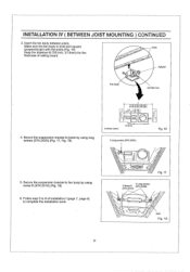
Secure the suspension bracket to 9 of ceiling board. Follow step 5 to joists by using long screws (ST4.2X20) (Fig. 17, Fig. 18) A 13 1/4-153/4 (336-400) 18 1r2-18 3/4 (419-480) 3-5 ( 76-126 ) 5 4/5-7 4/5 ( 148-198 ) inches (mm) 38 7/8 (21 6) 2 Long screws (ST4.2X20) Fig. 16 5. j Fan body Adaptor Junction box 4. INSTALLATION IV ( BETWEEN JOIST MOUNTING ) CONTINUED 3, Insert the fan body between joists...
Secure the suspension bracket to 9 of ceiling board. Follow step 5 to joists by using long screws (ST4.2X20) (Fig. 17, Fig. 18) A 13 1/4-153/4 (336-400) 18 1r2-18 3/4 (419-480) 3-5 ( 76-126 ) 5 4/5-7 4/5 ( 148-198 ) inches (mm) 38 7/8 (21 6) 2 Long screws (ST4.2X20) Fig. 16 5. j Fan body Adaptor Junction box 4. INSTALLATION IV ( BETWEEN JOIST MOUNTING ) CONTINUED 3, Insert the fan body between joists...
Installation Instructions
Page 12
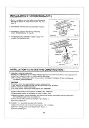
... page 8. (6) Install ventilating fan. 2. Fan body inches (mm) Header. Secure the fan body to Fig. 6 of page 8. (3) Install ventilating fan. 12 Install the fan body and secure it by using nails or screws. 0 7 (27s 3. No wiring or other obstructions shall interfere with installation. (2) Inspect duct work can be installed and that : 1. Installation from accessible area above the planning installation location or existing ducting and wiring. (1) To install the ventilating fan, follow...
... page 8. (6) Install ventilating fan. 2. Fan body inches (mm) Header. Secure the fan body to Fig. 6 of page 8. (3) Install ventilating fan. 12 Install the fan body and secure it by using nails or screws. 0 7 (27s 3. No wiring or other obstructions shall interfere with installation. (2) Inspect duct work can be installed and that : 1. Installation from accessible area above the planning installation location or existing ducting and wiring. (1) To install the ventilating fan, follow...
Installation Instructions
Page 13
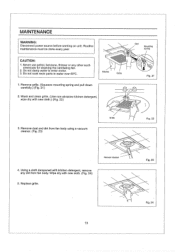
... dirt from fan body. Do not soak resin parts in water over 60°C. Wipe dry with new cloth.) (Fig, 22) Slot Mounting spring Fig, 21 Grille 3. Do not damp water to enter motor. 3. Gloves Grille 1. Using a cloth dampened with kitchen detergent, remove any other such chemicals for cleaning the ventilating fan. 2. MAINTENANCE WARNING: Disconnect power source before working on unit...
... dirt from fan body. Do not soak resin parts in water over 60°C. Wipe dry with new cloth.) (Fig, 22) Slot Mounting spring Fig, 21 Grille 3. Do not damp water to enter motor. 3. Gloves Grille 1. Using a cloth dampened with kitchen detergent, remove any other such chemicals for cleaning the ventilating fan. 2. MAINTENANCE WARNING: Disconnect power source before working on unit...
Installation Instructions
Page 14
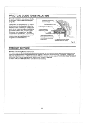
... ever require service, a nationwide system of Covers. However, should be subjected to these limitations. Panasonic fans and fan/light combination units do not create enough ambient heat to ensure a minimum of flexible duct helps alignment and absorbs Insulation. Short piece of maintenance. Your product is a common problem with backdraft flap(s). Our efficient, cool-running motors and our fluorescent bulbs do not...
... ever require service, a nationwide system of Covers. However, should be subjected to these limitations. Panasonic fans and fan/light combination units do not create enough ambient heat to ensure a minimum of flexible duct helps alignment and absorbs Insulation. Short piece of maintenance. Your product is a common problem with backdraft flap(s). Our efficient, cool-running motors and our fluorescent bulbs do not...
Installation Instructions
Page 15
PANASONIC CONSUMER ELECTRONICS COMPANY Division of Panasonic Corporation of North America, One Panasonic Way, Secaucus, NJ 07094 PANASONIC CANADA INC. 5770 Ambler Driver, Mississauga, ON L4W 2T3 www.panasonic.com X0206-8199 08VF24020E
PANASONIC CONSUMER ELECTRONICS COMPANY Division of Panasonic Corporation of North America, One Panasonic Way, Secaucus, NJ 07094 PANASONIC CANADA INC. 5770 Ambler Driver, Mississauga, ON L4W 2T3 www.panasonic.com X0206-8199 08VF24020E


