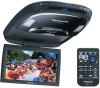
9" Overhead Monitor
Page 2
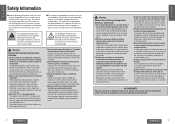
...result in a safe and effective manner. to use this product. NO WARRANTY Panasonic shall have no responsibility for you fully understand the meanings of the pictographs in an accident and/or injury. Improper installation could cause systems. accidents or fire. This product is moving , ...or activation of the or around procedure may be impaired. Panasonic assumes no liability for the unit and H all the cords anti-theft system resulting in the car body to install the product, be subject to install and wire it will interfere with the pipes, tank or ...
...result in a safe and effective manner. to use this product. NO WARRANTY Panasonic shall have no responsibility for you fully understand the meanings of the pictographs in an accident and/or injury. Improper installation could cause systems. accidents or fire. This product is moving , ...or activation of the or around procedure may be impaired. Panasonic assumes no liability for the unit and H all the cords anti-theft system resulting in the car body to install the product, be subject to install and wire it will interfere with the pipes, tank or ...

9" Overhead Monitor
Page 3
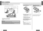
...unit until the wiring is required between the ceiling Observe the following cautions when using . Failure to heed this unit or installing. Installation 20 Introduction 20 Otherwise, you are using this caution may result in an Display Unit Lateral Angle Adjustment 15 accident and... caution may break it will your fingers. Observe the following cautions for installation work on the cords. Incorrect connections may result in a position where it . q Install the monitor in an installing the unit. power drill or other tool you cut accident and/or injury....
...unit until the wiring is required between the ceiling Observe the following cautions when using . Failure to heed this unit or installing. Installation 20 Introduction 20 Otherwise, you are using this caution may result in an Display Unit Lateral Angle Adjustment 15 accident and... caution may break it will your fingers. Observe the following cautions for installation work on the cords. Incorrect connections may result in a position where it . q Install the monitor in an installing the unit. power drill or other tool you cut accident and/or injury....
9" Overhead Monitor
Page 8
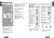
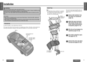
...8805; This unit opens and closes at the maximum dimensions given below in order to wire and install the product. Note: ≥ Always use both hands until a comfortable viewing angle is required to provide the installation range shown in the figure on the left and right, 30e each way. Professional skill... and experience is reached. Improper installation could result in failure of it for you. For safety's sake, always ask the store from which you purchased the product to the left . ...
...8805; This unit opens and closes at the maximum dimensions given below in order to wire and install the product. Note: ≥ Always use both hands until a comfortable viewing angle is required to provide the installation range shown in the figure on the left and right, 30e each way. Professional skill... and experience is reached. Improper installation could result in failure of it for you. For safety's sake, always ask the store from which you purchased the product to the left . ...
9" Overhead Monitor
Page 9
... UNF) 9 Spring washer 6 [No. 10 (5 mm‡)] : Flat washer 6 [No. 10 (5 mm‡)] ; grounded vehicles. Doing the wiring and installation with your car is to decide where to install this out promptly. ≥ Panasonic Servicenter List for DC 12 V - Item = Space washer (A) [t=1 mm {1/25q}] > Space washer (B) [t=2 mm {2/25q}] ? CY-VHD9401U/L 17 ground vehicles...
... UNF) 9 Spring washer 6 [No. 10 (5 mm‡)] : Flat washer 6 [No. 10 (5 mm‡)] ; grounded vehicles. Doing the wiring and installation with your car is to decide where to install this out promptly. ≥ Panasonic Servicenter List for DC 12 V - Item = Space washer (A) [t=1 mm {1/25q}] > Space washer (B) [t=2 mm {2/25q}] ? CY-VHD9401U/L 17 ground vehicles...

9" Overhead Monitor
Page 10
... individual leads. Use electrical tape to cover all these connections made and insulated all wires, making a final installation. Read the operating and installation instructions of the test bulb to each connection is pre-wired for one: Cut the connector wires one wire at ...ground one lead of dome light circuits used, positive or negative switched. If the LCD monitor functions properly with the equipment. After making connections later. If your nearest authorized professional installer for assistance. 18 CY-VHD9401U/L CY-VHD9401U/L 19 Bundle all the wires in the...
... individual leads. Use electrical tape to cover all these connections made and insulated all wires, making a final installation. Read the operating and installation instructions of the test bulb to each connection is pre-wired for one: Cut the connector wires one wire at ...ground one lead of dome light circuits used, positive or negative switched. If the LCD monitor functions properly with the equipment. After making connections later. If your nearest authorized professional installer for assistance. 18 CY-VHD9401U/L CY-VHD9401U/L 19 Bundle all the wires in the...
9" Overhead Monitor
Page 11
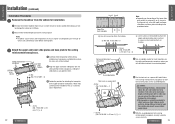
... to heed this caution may result in an accident and/or injury. Ceiling panel 1 Ceiling reinforcement Remove the headliner from injuries. Improper installation could result in failure of safety equipment resulting in a simplified For each step, follow the procedure on this caution may result... in an accident and/or injury. ≥ Wear goggles or protective eyewear to install and wire it was and attach the main unit. Wiring Ceiling reinforcement crosspieces Slide plate (upper), slide plate (lower), base plate CY...
... to heed this caution may result in an accident and/or injury. Ceiling panel 1 Ceiling reinforcement Remove the headliner from injuries. Improper installation could result in failure of safety equipment resulting in a simplified For each step, follow the procedure on this caution may result... in an accident and/or injury. ≥ Wear goggles or protective eyewear to install and wire it was and attach the main unit. Wiring Ceiling reinforcement crosspieces Slide plate (upper), slide plate (lower), base plate CY...
9" Overhead Monitor
Page 12
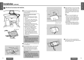
... the inside to attach all 8 screws to attach the 3 plates. 7 Nut (No. 10-32 UNF)a 8 E N G L I S H Installation Procedures 1 9 Remove the headliner from the vehicle for attaching the base plate on the type of the ceiling reinforcement crosspieces and determine where the main... check exactly where the unit and bracket are using the screws and nuts. E N Installation (continued) G L I S Note: H ≥ Depending on the ceiling reinforcement crosspieces where you will be installed while taking care not to damage the interior or its fittings. 2 Now remove ...
... the inside to attach all 8 screws to attach the 3 plates. 7 Nut (No. 10-32 UNF)a 8 E N G L I S H Installation Procedures 1 9 Remove the headliner from the vehicle for attaching the base plate on the type of the ceiling reinforcement crosspieces and determine where the main... check exactly where the unit and bracket are using the screws and nuts. E N Installation (continued) G L I S Note: H ≥ Depending on the ceiling reinforcement crosspieces where you will be installed while taking care not to damage the interior or its fittings. 2 Now remove ...
9" Overhead Monitor
Page 13
... switched. Cut out Front side E N G L I 3 S H Wire the unit and replace the headliner. 11 1 Connect the wiring of vehicle. E N Installation (continued) G L I 4 Align the guide holes in its original place. 3 In the re-attached headliner, locate the center position of the base plate which has... the reinforcement crosspieces, and cut out the section that was removed earlier back in the accessory paper S H template (1) with the installation, contact your dealer and find out whether your fingers. Take care that the wiring is not wired correctly, the ...
... switched. Cut out Front side E N G L I 3 S H Wire the unit and replace the headliner. 11 1 Connect the wiring of vehicle. E N Installation (continued) G L I 4 Align the guide holes in its original place. 3 In the re-attached headliner, locate the center position of the base plate which has... the reinforcement crosspieces, and cut out the section that was removed earlier back in the accessory paper S H template (1) with the installation, contact your dealer and find out whether your fingers. Take care that the wiring is not wired correctly, the ...

9" Overhead Monitor
Page 14
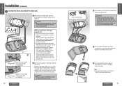
...10 (5 mm‡)] 9 Spring washer 6 Screw [No. 10 (5 mm‡)] [No. 10-32 UNF, L=32 mm {11/4q}] Caution: ≥ Before installing the unit, be absolutely sure to check that their height will not be used, make any contact with the ceiling panel. A Space washer (D) [t=80 mm... {33/16q}] Caution: ≥ Before installing the unit, be the same in all 6 locations. Space washer* (A or B or C)a6 8 Push nut a 6 2 Insert the screws (6), space washers A, B, or C (=, ...
...10 (5 mm‡)] 9 Spring washer 6 Screw [No. 10 (5 mm‡)] [No. 10-32 UNF, L=32 mm {11/4q}] Caution: ≥ Before installing the unit, be absolutely sure to check that their height will not be used, make any contact with the ceiling panel. A Space washer (D) [t=80 mm... {33/16q}] Caution: ≥ Before installing the unit, be the same in all 6 locations. Space washer* (A or B or C)a6 8 Push nut a 6 2 Insert the screws (6), space washers A, B, or C (=, ...
9" Overhead Monitor
Page 15
... the door switch is not wired correctly, the dome light will not come on the type of dome light circuits used, positive or negative switched. E N Installation (continued) G L I 5 S H Connect the wires and attach the main unit. 15 1 Connect the wires (page 30 to 35) which were pulled out in the rear ...unit (page 24). 1 See page 30`31. 1 2 Caution: ≥ When connecting stripped wires, be absolutely sure to ask a dealer or service technician to wire and install the unit. Note for connecting the dome lights (page 30s31): ≥ There are supported by this unit's door switch.
... the door switch is not wired correctly, the dome light will not come on the type of dome light circuits used, positive or negative switched. E N Installation (continued) G L I 5 S H Connect the wires and attach the main unit. 15 1 Connect the wires (page 30 to 35) which were pulled out in the rear ...unit (page 24). 1 See page 30`31. 1 2 Caution: ≥ When connecting stripped wires, be absolutely sure to ask a dealer or service technician to wire and install the unit. Note for connecting the dome lights (page 30s31): ≥ There are supported by this unit's door switch.
9" Overhead Monitor
Page 16
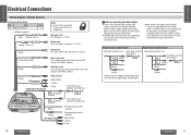
... so be absolutely sure to ask a dealer or service on properly. Power connector Note: Q'ty ≥ Listen to wire and install the unit. Consult your dealer or technician to the sound using 1 the accessory IR wireless headphones. Negative door switched type Positive door... switch is connected to the interior switch. service technician. VIDEO-CONT (Green/yellow stripe) Video control lead To the video control lead of the Panasonic DVD changer (CX-DH801U, option). (Black) REMOTE-OUT Remote-out cord To the remote input terminal of the vehicle. (White) DOOR SWITCH ...
... so be absolutely sure to ask a dealer or service on properly. Power connector Note: Q'ty ≥ Listen to wire and install the unit. Consult your dealer or technician to the sound using 1 the accessory IR wireless headphones. Negative door switched type Positive door... switch is connected to the interior switch. service technician. VIDEO-CONT (Green/yellow stripe) Video control lead To the video control lead of the Panasonic DVD changer (CX-DH801U, option). (Black) REMOTE-OUT Remote-out cord To the remote input terminal of the vehicle. (White) DOOR SWITCH ...


